How to Connect the LED Backlight

Connect the LED backlight to Character LCD Displays:
This article will be limited to character LCD Displays and the three methods available to connect the LED backlight to a power source. All three methods will work, but not all are recommended.

“ Will your LCD display require a backlight?” This is one of the first questions we ask customers when designing a new LCD Display and for good reason. The majority of character (alphanumeric), segment (static) and monochrome graphic (dot matrix) LCD displays operate in low lighting conditions and require a LED (Light Emitting Diode) backlight.
Other Display technologies such as TFT displays contain a built-in backlight that is on when the display is active and OLED Displays generate their own light and do not require a backlight.
Method #1: Connect the LED backlight via pins 15 & 16
The most common method to supply power to the LED backlight is through pins 15 and 16 of the header. This is the preferred method since all power and signal connections can be made through one header/ IDC cable reducing assembly cost. Also the supply voltage for the LED is independent of the Logic voltage of the LCD (VLCD). This is to help eliminate any noise in the circuit.
The interface table below shows pin 15 (Anode) to be positive and pin 16 (Cathode) to be ground.

REVERSED POLARITY OF THE LED BACKLIGHT:
I would estimate that 50% of the LCD displays equipped with a LED backlight have pin 15 set to positive and pin 16 set to ground, with the reverse being true for the other 50% of the LCD modules. If you power up your LCD and find the display works, but the backlight is dark, then the LCDs backlight polarity is reversed.
This is a simple fix and is accomplished by reversing the jumper settings on the PCB (Printed Circuit Board). If you would like help, contact our US based technical support people at 480-503-4295.
Method #2: Connect the LED backlight via A & K
The second most popular option to drive the LED backlight is through the A and K pins located on the side of the LCD module. The A stands for Anode and is the positive side of the LED backlight, the K stands for Cathode (yes it’s spelled with a C, but uses the letter K, but that’s an entirely different subject.)
This is a common praxis when the LCD only contains fourteen pins and not the extra two pins (15 and 16) for the backlight.
The image below shows the connection pins on the right side of the PCB and are labeled ‘+ ‘and ‘– ‘. Some PCBs (Printed Circuit Boards) will label the ‘+’ (A ) and the ‘-‘ (K) and in some instances: ground.
Many OEMs prefer to add a separate cable to the A and K with the goal of supplying an independent power and ground to the backlight. This is a good method if your backlight voltage is different than your LCD logic voltage, or if you require two independent grounds between the LCD logic and the backlight. Two common methods for connecting the A and K are: through a pigtail as seen in the photo below or with a two position header to mates to the customers PCB.

A majority of character displays have the A connected to pin 15 and the K connected to pin 16 through traces in the PCB. If you need these traces disconnected to reverse polarity, many of the PCBs contain jumpers that can be unsoldered to create an open circuit. If the PCB does not contain this jumper, we can redesign the board to separate A and K from pins 15 and 16.
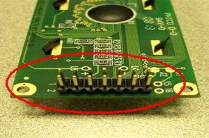
Method #3: Connect the LED backlight via pins 1 & 2
This is the least popular and least recommended option. Power for the LED backlight is drawn from the same source that supplies the LCD logic. Many times this is done after the design is completed and the LED backlight was an afterthought.
As a general rule, it is good to separate the VLCD (Voltage required by the LCD) power from your VLED (Voltage required by the LED backlight) power.
Do you have questions about your next LCD Design? We can help. Call us at: 480-503-4295.