Connecting External Capacitors to a Graphic LCD
In this application note we will discuss how to power a graphic LCD that requires external capacitors to boost the voltage required for this display. Some graphic displays will need to be connected to external capacitors while some have the capacitors built into their internal hardware. The capacitors are used for a DC/DC voltage converter and booster that increases the voltage for the LCD to display pixels. It is important to consult the data sheet for the display to determine if the external capacitors are required for setup.
1. Introduction
The display used in this application is a 128×64 pixel display that requires 5V for the backlight, 9V for the LCD pixels and 3.3V for the logic. This is where the capacitors come in, to boost the 3.3V to approximately 9V depending on the configuration. We will also use an Arduino to provide the external power and for the logic. Below is an overview of the display we will be using. As always, check the data sheet to determine pin outs, voltage ratings and interface settings. (data sheet)
- 30 pins, 72x46x4.2mm
- 128×64 pixels, FSTN
- ST7565P controller
- Yellow Backlight
- Transflective (positive)
- Serial and Parallel interfaces
- Built in DC-DC voltage converter
2. What You’ll Need
2a. First and foremost you will need to Download the Arduino IDE software if you have not already. Alternatively, you can use the cloud-based version: “Ardunio Web Editor”. We will come back to this program after we have the display wired up.
2b. Below is a list of the physical materials you will need to setup the project.
| Qty | Description | Note |
| 1 | Arduino UNO (Rev 3) with USB Cable | Arduino |
| 1 | G126GLGFYSY6WT Graphic LCD | FocusLCDs |
| 1 | Solderless Breadboard | |
| 1 | Male-to-Male Jumper Wires (Set) | |
| 8 | 1µF Capacitors | |
| 1 | 30-pin FPC connector board 0.5mm pitch | |
| 1 | Soldering Iron | |
| 1 | Solder |
3. Wiring
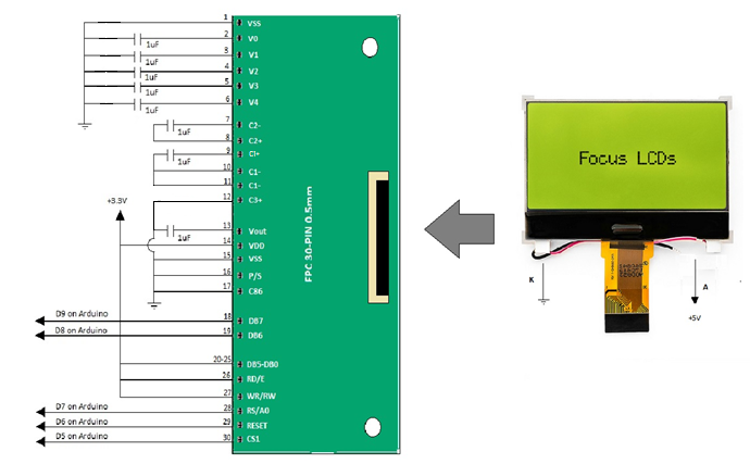
This project requires a brief amount of soldering to connect wires to the 30-pin FPC adapter board. We need to connect 8 external capacitors to pins 2-12. There are a few configurations for setting up the voltage booster circuit. For this project we will use the 3x step-up voltage circuit. Below are some variations for the circuit depending on the required voltage.

Below is a diagram representing how the graphic LCD should be wired and connected to the Arduino and the external capacitors. The LCD has a ribbon connector and therefore you will need a 30-pin FPC adapter in order to connect external wires. In the diagram below the external capacitors are arranged in the 3x boost voltage circuit which will produce approximately 9.9V. You can measure this at pin 13 (Vout) with a digital multimeter.

4. Pin Description
The following table is the description of each of the output pins of the LCD and their connection to the Arduino and breadboard. For further clarification, check the data sheet of the display and controller for voltage ratings and pin assignments. The unused data pins in this circuit need to be pinned HIGH when not in use.
For this example, I have chosen to use the serial interface because there are fewer pins to connect. This display has the option for a parallel interface for a faster data transmission however you would need to connect all the data buses. You will also need to connect 9 external capacitors for the voltage booster circuit. It is necessary to boost the input voltage to approximately 9V for the LCD to be driven.

The backlight circuit will need a ~ 60Ω resistor between the input voltage to adjust current to approximately 80mA which is the recommended current for these LED’s. Check the data sheet of the display to verify if you need additional resistance. You can adjust the brightness of this backlight depending on these values.
5. Programming the Arduino
Now it is time to program the display using the Arduino IDE. Plug in the display ribbon to the FPC and the Arduino to the computer. You should see the yellow/green backlight come on. To run an example program on the display we will need a code specific to the driver in the display. This is a pretty common controller so there are a lot of open source coding options for examples.
The one I have chosen is from Adafruit, they have preprogrammed the registers and settings for the ST7565P driver and have a quick example.
Download the library from GitHub and add it to the Arduino libraries folder of the IDE. Or find the library in the “manage libraries” section of the Arduino IDE program. The name of the program we will be using is ST7565-LCD .
After you have the program downloaded and in the Arduino libraries folder, open up the example titled “st7565lcd”. The example should look like the following with the serial data pins connected to the Arduino and defined in the statement:
ST7656 glcd(7,11, 10,9,8);
You will need to change this in order to reference the pins that we have chosen or change your connections to the Arduino. The code specific to our setup will be changed to:
ST7656 glcd(9,8,7,6,5);
As seen below:

There is the option of turning on and off the backlight through a digital pin, but I have chosen not to use this function. This could be a good option if you are using a battery to save power on the backlight.
This driver has an internal voltage regulator circuit included which means that we can control the resistance and thus the contrast of the pixels through commands in the Arduino program. This is can be changed by altering this line in the program:

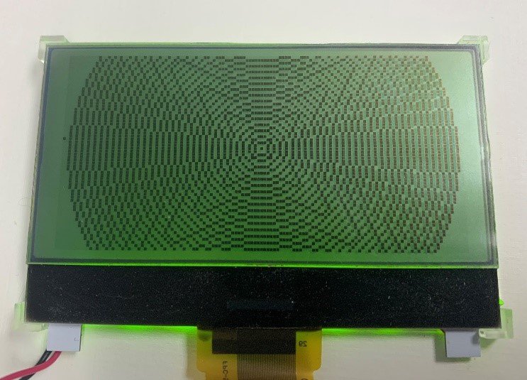
Now it’s time to run the example. If everything is setup correctly you should see the example as displayed below. It will run through a few test example screens exhibiting the typical functions of a graphic display.


6. Debugging
If your program is not displaying correctly there are a few places you might want to check first.
If you have an inverted image, you may need to change a function in the “ST7565.cpp” file. To do this you will need to go to the file location and edit the “ST7565.cpp” file using an editor. The changed version should appear as follows:
const uint8_t pagemap[] = { 7, 6, 5, 4, 3, 2, 1, 0 };
Make sure to save these changes before re-running the program.
There are a lot of good debugging tools in this example program . Try finding a solution in the serial monitor with some of these debugging features by adding a few “Serial.print()” functions to see what’s going on. It is also a good jumping off point for other projects displaying bitmaps and a variety of characters.
If you are having low contrast or are not seeing pixels, it may be that you have a problem with the wiring of the voltage booster circuit. Verify that pin 13 ”Vout” is reading at least 9 volts at its pin by using a DMM. If it does not have this stepped-up voltage you will not see any pixels or there will be very little contrast. Be sure to check capacitance connections or resort to a different variation of the boost circuit. Alternatively, you can adjust the contrast in the software thanks to the internal voltage regulating circuit.
7. Summary
There are many types of graphic displays available and some may require a voltage boost using external capacitors. Most displays that require a step-up voltage will instruct how to connect the capacitors in the data sheet for your controller. There are a few variations of voltage boosting circuits depending on how many times you need to step-up the supply voltage. Not enough voltage will result in low contrast of the pixels. Not all graphic displays require external capacitance to be added. It is always important to check the data sheet to verify if they have already been integrated into the circuit of the display and how much voltage you will require.
DISCLAIMER
Buyers and others who are developing systems that incorporate FocusLCDs products (collectively, “Designers”) understand and agree that Designers remain responsible for using their independent analysis, evaluation and judgment in designing their applications and that Designers have full and exclusive responsibility to assure the safety of Designers’ applications and compliance of their applications (and of all FocusLCDs products used in or for Designers’ applications) with all applicable regulations, laws and other applicable requirements.
Designer represents that, with respect to their applications, Designer has all the necessary expertise to create and implement safeguards that:
(1) anticipate dangerous consequences of failures
(2) monitor failures and their consequences, and
(3) lessen the likelihood of failures that might cause harm and take appropriate actions.
Designer agrees that prior to using or distributing any applications that include FocusLCDs products, Designer will thoroughly test such applications and the functionality of such FocusLCDs products as used in such applications.
1Arduino is an open-source development platform for easily building electronics projects that can electrically sense and control other objects. Arduino boards are primarily based on the Atmel AVR (8-bit) microcontroller (Example: Arduino UNO).