Drawing Bitmaps with the E43RG34827LW2M300-R TFT
This is a quick-start guide to drawing bitmaps on the E43RG34827LW2M300-R TFT. It requires familiarity with using an Arduino.
1. Introduction
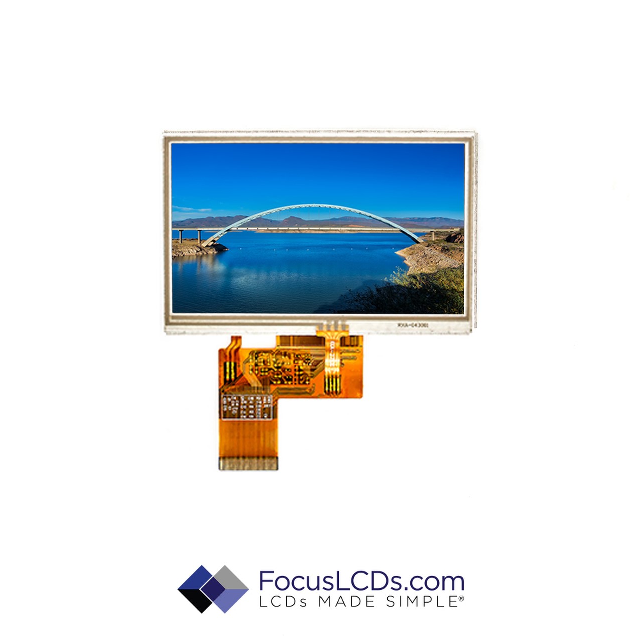
The E43RG34827LW2M300-R is a color active matrix TFT (Thin Film Transistor) LCD (liquid crystal display) that uses amorphous silicon TFT as a switching device. This model is composed of a transmissive type TFT LCD panel, driver circuit, and backlight. The resolution of a 4.3” TFT LCD contains 480×272 pixels and can display up to 16.7M colors.
Summary of Features
- 40 pins, 105.4 mm x 67.15 mm
- 8/16/18/24-bit RGB
- ILI6408B Driver IC
- White LED Backlight
- Top viewing angle (12 ‘o clock)
- Operating temperature of: -20ºC to +70ºC, Storage temperature of: -30ºC to +80ºC
- Transmissive polarizer
- 4-wire resistive touchscreen
- ROHS compliant

Figure 1: E43RG34827LW2M300-R TFT Display Module
2. The RA8875 Driver Board
The RA8875 Driver board is capable of driving 4”, 5” and 7” 40-pin TFTs with up to 800×480 pixels. It can be used with the Arduino and features 60Hz refresh rate, 4 MHz pixel clocking and a resistive touchscreen. It contains 768KB of RAM for buffering the display. The interface uses SPI and has a selection of hardware-accelerated shapes like ellipses, triangles, and rectangles. Moreover, it has a built-in English/European font set.
The RA8875 has the ability to handle 4-wire resistive touchscreens over SPI. Also included is an interrupt pin (IRQ) to take care of touch interrupts. 3-5V power can be used via on-board level-shifting and includes a constant-current boost power supply which provides 25mA or 50mA at 24V to the backlight.
Caution: Not all 40-pin TFTs may work with this board and may even damage it or the TFT itself because of different pinouts and backlight management. 24V from the boost supply may be inadvertently applied to the logic pins. So please check the TFT datasheet first.

Figure 2: RA8875 Driver Board (Credit: Adafruit).
3. What You Need
| Qty | Description | Store |
| 1 | Arduino UNO (Rev 3) with USB Cable | Arduino |
| 1 | E43RG34827LW2M300-R TFT Display Module | FocusLCDs |
| 1 | Solderless Breadboard | Adafruit |
| 1 | Male-to-Female Jumper Wires (Set) | Adafruit |
| 1 | RA8875 Driver Board | Adafruit |
| 1 | Arduino Data-Logger Shield | Adafruit |
| 1 | Arduino IDE | Arduino |
4. Instructions
4.a Note that this application note requires knowledge in using the Arduino and its shields.
4.b Wire up the circuit as shown in the following schematic (Figure 3). The Datalogger or Ethernet Shield is plugged on top of the Arduino UNO. The actual setup is shown in Figure 4.
4.c Prepare the bitmap image. It should 480×272 pixels with 24-bit pixel format.
4.d Save that image on the SD card. The filename should be equal or less than 8 characters. In this example, the name: “flcdlog0.bmp” was used (see line 69 of the sketch). You can use another image or filename.
4.e Insert the SD card into the slot of the shield.

Figure 3: Schematic of Arduino, RA8875 and TFT display module.

Figure 4: Actual setup based on the schematic.
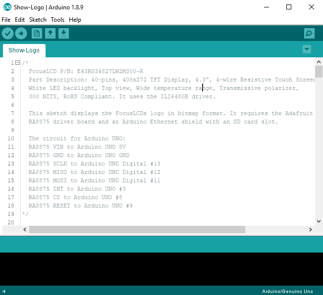
4.e Open this arduino program (AKA Sketch): Show-Logo.ino

Figure 5: Arduino IDE and Sketch.
Important:
- The RA8875 CS (Chip Select) pin is connected to pin 8 of the Arduino.
- The Datalogger or Ethernet Shield CS pin is connected to pin 10 of the Arduino. Typically, for these shields pin 10 is usually hard-wired.
- The Ethernet Shield used in this example contains an SD card.
- In line 49 of the sketch, you have to set the resolution (size) e.g. ‘RA8875_480x80’, ‘RA8875_480x128’, ‘RA8875_480x272’ or ‘RA8875_800x480’. In this case, it is ‘RA8875_480x272’.
4.g Specify Arduino UNO is used and select the correct PC COM port. In the IDE top menu, select Tools > “Board: Arduino / Genuino UNO”. Then again, Tools > Port. Usually, it is COM3.
4.h Upload to run the sketch. The LCD should have a display like in Figure 6. It will take approximately 35-40 seconds for the bitmap to be drawn.

Figure 6: Drawn bitmap on the TFT display module.
5. Summary
The E43RG34827LW2M300-R TFT has a wide-array of applications apart from this simple example of drawing bitmaps. It has been demonstrated that it can work with an Arduino via the RA8875 board. More complicated designs can be derived from this application note.
In future application notes, other 40-pin TFT display modules will be showcased using this method.
DISCLAIMER
Buyers and others who are developing systems that incorporate FocusLCDs products (collectively, “Designers”) understand and agree that Designers remain responsible for using their independent analysis, evaluation and judgment in designing their applications and that Designers have full and exclusive responsibility to assure the safety of Designers’ applications and compliance of their applications (and of all FocusLCDs products used in or for Designers’ applications) with all applicable regulations, laws and other applicable requirements.
Designer represents that, with respect to their applications, Designer has all the necessary expertise to create and implement safeguards that:
(1) anticipate dangerous consequences of failures
(2) monitor failures and their consequences, and
(3) lessen the likelihood of failures that might cause harm and take appropriate actions.
Designer agrees that prior to using or distributing any applications that include FocusLCDs products, Designer will thoroughly test such applications and the functionality of such FocusLCDs products as used in such applications.