The GT911 is a capacitive touch controller used in embedded systems for its precision and versatility. It supports up to 5-point multi-touch with high accuracy and fast response times. The GT911 also supports several built-in gesture recognitions, including swipe, multi-press, and pinch.
The controller features adjustable resolution, configurable touch sensitivity, and advanced noise immunity, making it ideal for modern touch-based applications. With its I2C interface, the GT911 simplifies integration into a variety of embedded platforms.
Introduction
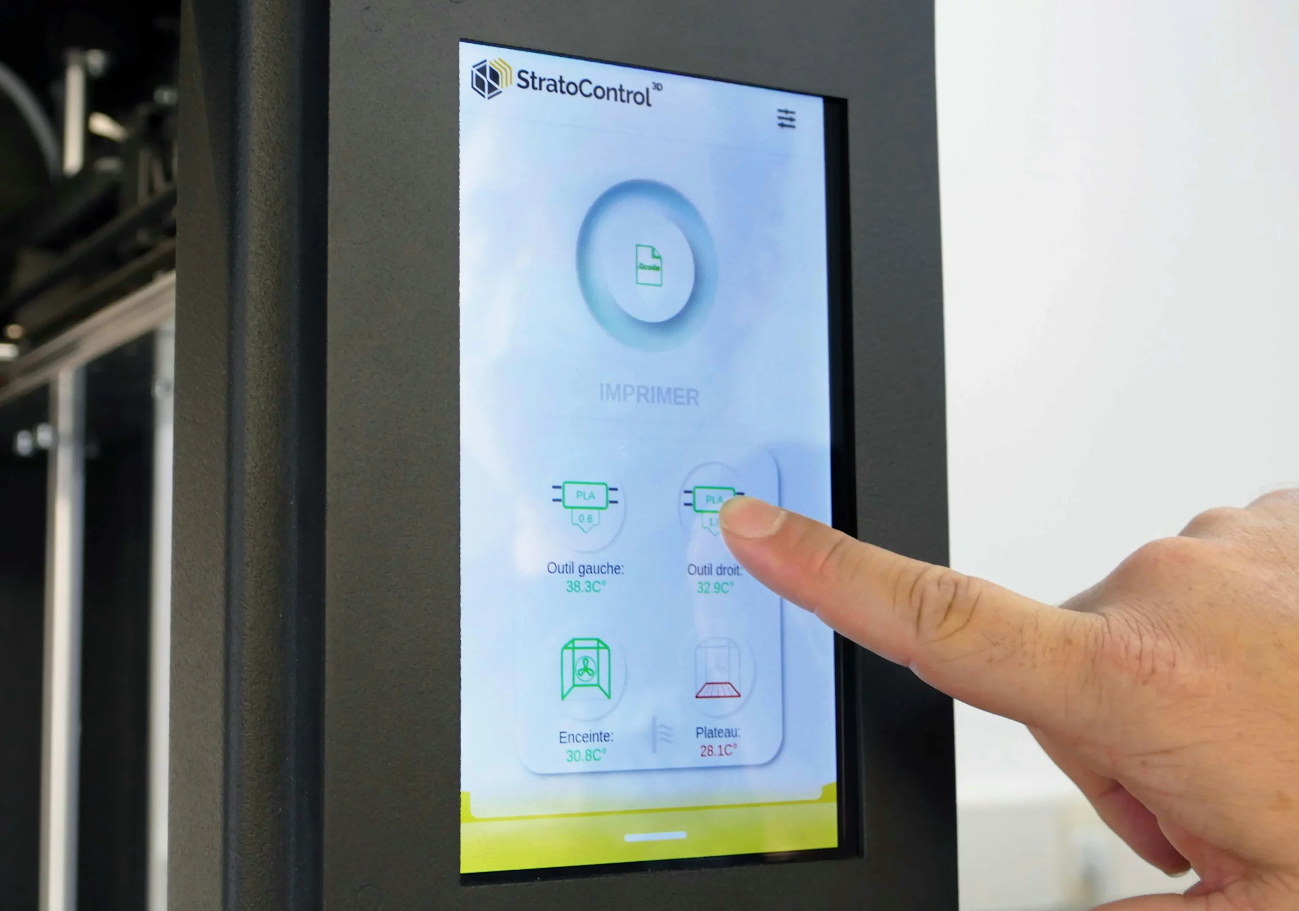
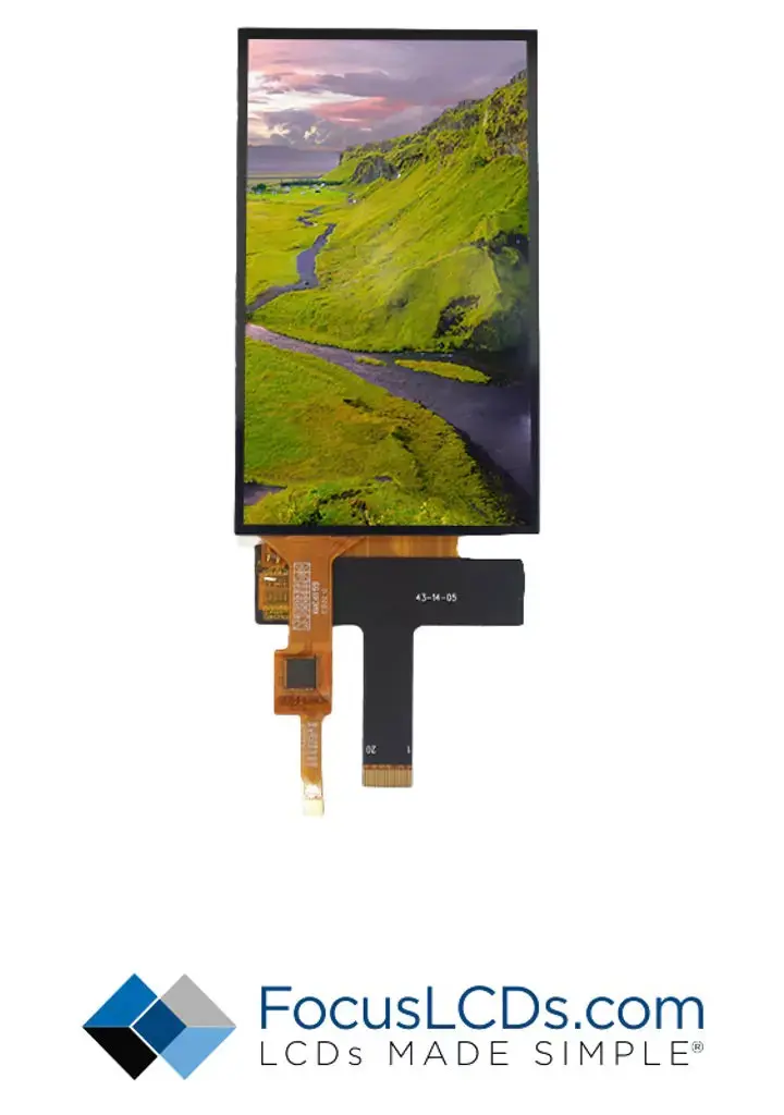
This application note focuses on using the GT911 touch controller in conjunction with the STM32H747I-DISCO development board and the Focus LCDs E43GB-I-MW405-C display. The E43GB-I-MW405-C is a 4.3-inch TFT LCD with a resolution of 480 x 800 pixels, offering bright and vivid visuals for user interfaces. The display includes the GT911 capacitive touch controller, enabling responsive and precise touch input across its surface.
The STM32H747I-DISCO development board, based on the STM32H747 dual-core microcontroller, provides powerful processing capabilities and a rich set of peripherals. Its I2C4 peripheral is utilized for communication with the GT911 touch controller. The I2C4 interface operates with flexible clock configurations, supports multiple addressing modes, and integrates robust error handling, making it well-suited for handling touch data efficiently.
The driver code being developed in this application note takes advantage of the ARM CMSIS header files and some of the low-level STM32 HAL code for peripheral initialization. The GT911, Touch, and higher-level code is of a bare-metal design to facilitate adapting to other microcontroller platforms. Only the low-level peripheral code is dependent on the MCU architecture.
Contact Focus LCDs for more information on the Touch controller and firmware.
This document covers:
- Initializing the I2C4 peripheral on the STM32H747I-DISCO.
- Configuring and initializing the GT911 touch controller.
- Reading and writing data to the GT911 touch controller via I2C.
- Developing application-level code to process touch events and report X/Y coordinates.
- Programming gesture recognition.
Watch our video showing the functional results of this program on YouTube
GT911
The GT911 is a high-performance capacitive touch controller manufactured by Goodix Technology supporting multi-touch and gesture detection.
Key features include:
- Support for up to 5-point multi-touch detection
- Built-in touch key functionality
- 32-bit CPU core for efficient touch processing
- Automatic calibration and drift compensation
- Low power consumption modes:
- Normal working current: 3.5mA (typical)
- Sleep mode current: < 50μA
- Hibernation current: < 10μA
- Operating voltage range: 2.8V to 3.3V
- Sampling rate up to 100Hz
- High noise immunity and interference resistance
- Built-in voltage regulator
- Support for various screen sizes up to 10 inches
- I2C communication interface up to 400 kHz
- Programmable interrupt trigger conditions
Focus LCDs E43GB-I-MW405-C
The Focus LCDs E43GB-I-MW405-C is a 4.3-inch TFT LCD module with integrated GT911 capacitive touch controller.
Display Characteristics:
- 4.3-inch TFT LCD panel
- Resolution: 480 x 800 pixels (portrait orientation)
- 16.7M colors (24-bit RGB interface)
- LED backlight with 500 cd/m² typical brightness
- Viewing angle: 80°/80°/80°/80° (L/R/U/D)
- Operating temperature: -20°C to +70°C
Touch Panel Specifications:
- GT911 capacitive touch controller
- 5-point multi-touch capability
- I2C interface (address 0xBA)
- 2mm cover glass thickness
- >85% optical transparency
- Surface hardness: 6H
- Touch response time: <5ms
- Position reporting accuracy: ±2mm
STM32H747I-DISCO Dev Board I2C Peripheral Specification
The STM32H747I-DISCO development board features multiple I2C interfaces with the following capabilities:
- Four I2C interfaces (I2C1, I2C2, I2C3, and I2C4)
- Support for Standard Mode (SM, up to 100 kHz)
- Support for Fast Mode (FM, up to 400 kHz)
- Fast Mode Plus (FM+, up to 1 MHz) on all I2C peripherals
- Programmable digital noise filters
- Programmable analog noise filters
- SMBus 2.0/PMBus compatible
- Programmable timings and duty cycles
- DMA support for efficient data transfer
- Dual addressing capability
- 7-bit and 10-bit addressing modes
- Hardware CRC calculation
This application note will walk through the implementation process, providing detailed C code snippets and explanations for each critical step integrating the GT911 touch controller on the Focus LCDs E43GB-I-MW405-C display with the STM32H747I-DISCO board.
I2C Communication
The GT911 touch controller communicates via I2C, specifically using I2C4 on the STM32H747I-DISCO board with a device address of 0xBA and a maximum clock speed of 400kHz. In this application the standard clock speed of 100kHz will be used for reliable operation.
The driver being developed includes error handling, timeout management, and proper peripheral initialization. It’s configured for 100 kHz standard mode operation but can be adjusted for fast mode (400 kHz) by modifying the timing parameter in I2C_Init.
I2C Peripheral Initialization
The process of initializing the I2C peripheral on the STM32H7474I-DISCO includes configuring the GPIO pins, initializing the I2C4 peripheral, and finally establishing I2C communications.
I2C4 Hardware and Pin Mapping
I2C4 is another I2C peripheral available on the STM32H747. On the STM32H747I-DISCO development board, I2C4 is typically mapped to the following pins:
- PD12 for I2C4_SCL (Clock Line)
- PD13 for I2C4_SDA (Data Line)
Check the board schematics to confirm the pin assignments and ensure no conflicts with other peripherals or features using these pins.
GPIO for I2C4
The GPIO pins used for I2C4 must be configured as alternate functions to support I2C communication. Proper pin configuration ensures signal integrity and compatibility with the GT911 touch controller.
- Set PD12 and PD13 as GPIO_MODE_AF_OD (alternate function open drain). This configuration is essential for bidirectional communication on the I2C bus.
- Enable the internal pull-up resistors (GPIO_PULLUP) on both pins to keep them in a known state during idle conditions.
- Set the GPIO speed to “Fast” or “High” for high-frequency I2C communication.
- Assign the alternate function for I2C4:
- PD12 – AF4_I2C4
- PD13 – AF4_I2C4
Ensure external pull-up resistors (typically 2.2 kΩ up to 4.7 kΩ) are connected to the I2C bus lines if internal pull-ups are insufficient for reliable operation.
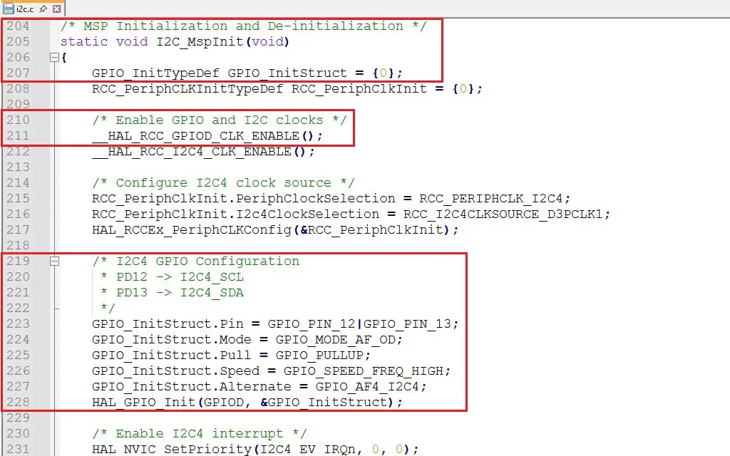
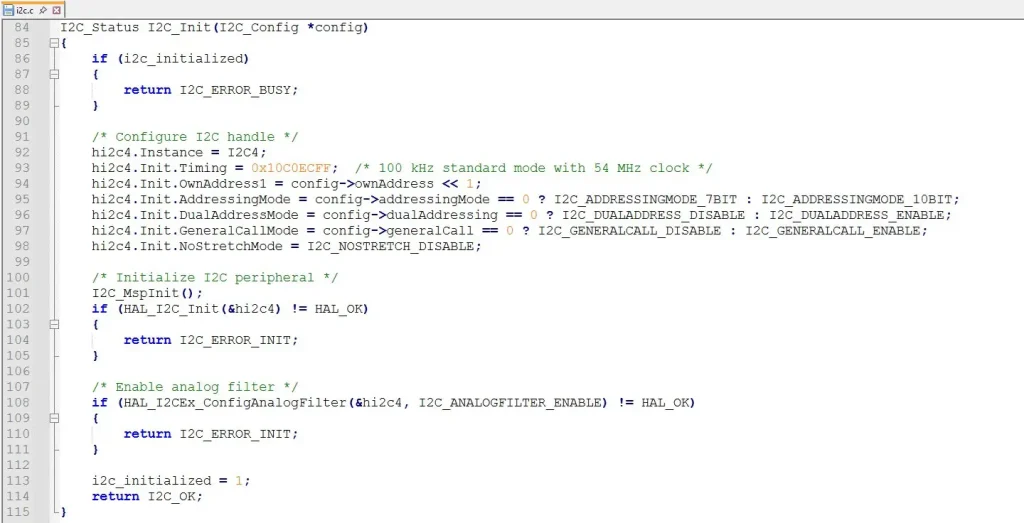
The function I2C_MspInit() creates a GPIO structure for configuring the IO pins. Once that structure is initialized the RCC clock for the GPIO peripheral is enabled. The next step is to populate the GPIO structure with the configuration to enable I2C on pins 12 and 13.
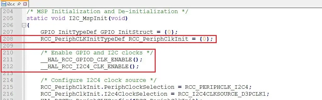
Enabling the I2C4 Peripheral Clock
Before using the I2C4 peripheral, its clock source must be enabled through the RCC (Reset and Clock Control).
- Use the appropriate macro to enable the I2C4 clock, such as HAL_RCC_I2C4_CLK_ENABLE() in the HAL library.
- Verify that the clock for GPIO port D is also enabled, as I2C4 pins are connected to this port. For example:
- HAL_RCC_GPIOD_CLK_ENABLE()
Enabling these clocks ensures the GPIO and I2C peripherals can operate correctly.
Initialize the I2C4 Peripheral
The I2C4 peripheral must be initialized with settings compatible with the GT911 touch controller. This includes:
- Clock Speed: Set the I2C clock speed based on the GT911’s requirements, such as 100 kHz (Standard Mode) or 400 kHz (Fast Mode).
- Addressing Mode: Configure I2C4 for 7-bit addressing, as the GT911 typically uses a 7-bit slave address (e.g., 0x5D [0xBA/0xBB] or 0x14 [0x28/0x29]).
- Timing Configuration: Calculate the timing register values using STM32CubeMX or manually determine them based on the reference manual. This configuration depends on the I2C clock source, peripheral clock frequency, and desired I2C speed.
- Initialization: Use HAL, LL (Low-Level) drivers, or direct register manipulation to initialize the I2C4 peripheral. Specify parameters such as the clock speed, addressing mode, and timing values.
Establish and Validate I2C Communications
Once the I2C4 peripheral is initialized, you can communicate with the GT911 touch controller. The typical order of events is:
- Generate a Start Condition: The master (STM32H747) generates a start condition by pulling the SDA line low while SCL remains high.
- Send the Slave Address: Send the 7-bit GT911 address followed by the R/W bit (0 for write, 1 for read).
- Exchange Data: Transmit or receive data in 8-bit chunks. For each byte sent, the slave must send an acknowledgment (ACK).
- Generate a Stop Condition: The master releases the SDA line to high while SCL is high to signal the end of communication.
After configuring the I2C4 peripheral, verify the setup to ensure successful communication with the GT911. Use an oscilloscope or logic analyzer to monitor the SDA and SCL lines. Inspect the traffic for proper waveforms and timings on PD12 (SCL) and PD13 (SDA). Verify the presence of pull-up resistors (internal or external, typically between 2.2kΩ to 4.7kΩ, but could be as high as 10kΩ) on the I2C lines. Finally, test the basic read and write operations to ensure that the GT911 responds correctly to its I2C address.
Handling Errors and Debugging
I2C communication issues can occur due to electrical noise, incorrect configuration, or addressing errors. Implement robust error handling:
- Check for acknowledgments (ACK/NACK) after every data frame.
- Handle bus errors, arbitration losses, or timeouts using HAL or custom routines.
- Implement retry mechanisms for transient failures.
GT911 Capacitive Touch Controller Overview
The GT911 is a capacitive touch controller that communicates via the I2C bus. It supports up to 5 touch points and offers flexible configuration for screen resolution and touch parameters.
Key features include: I2C slave mode with a default 7-bit address, configurable resolution and orientation, and registers for status, configuration, and touch data.
GT911 Configuration and Registers
GT911 I2C4 Connections and Pin Mapping
The GT911 is connected to the STM32H747I-DISCO’s I2C4 peripheral as follows:
- I2C4 SCL (Clock Line): PD12 – configured in the I2C code.
- I2C4 SDA (Data Line): PD13 – configured in the I2C code
- Interrupt Line: PK7 (used to detect touch events).
- Reset Line: PG3 (used to reset the GT911).
- Configure PK7 as an input pin for interrupt detection.
- Configure PG3 as an output pin for resetting the GT911.
Verify these pin connections on the development board and ensure no pin conflicts.
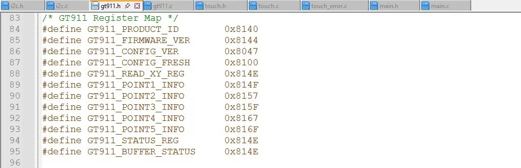
GT911 Register Map and Overview
The GT911 touch controller features a comprehensive internal register map for configuration and control. Key register sections include:
| Register Range | Description | Access |
| 0x8040 – 0x8046 | Command and Status | R/W |
| 0x8047 – 0x80FF | Configuration | R/W |
| 0x8100 – 0x813F | Coordinate Data | R |
| 0x8140 – 0x814E | Product ID and Information | R |
| 0x814F – 0x8156 | Touch Point Data | R |
| 0x8157 – 0x81FF | Reserved | – |
GT911 Register Configuration
Key registers for GT911 configuration:
GT911 Initialization
The initialization of the GT911 begins with configuring the I2C peripheral on the STM32H747I-DISCO board. The I2C interface is enabled and set to operate at either standard (100kHz) or fast (400kHz) mode, depending on system requirements.
GPIO pins for the INT and RESET lines must also be configured. The RESET pin is set as an output, while the INT pin is configured as an open-drain output. The default state for these pins is High for RESET and Low for INT.
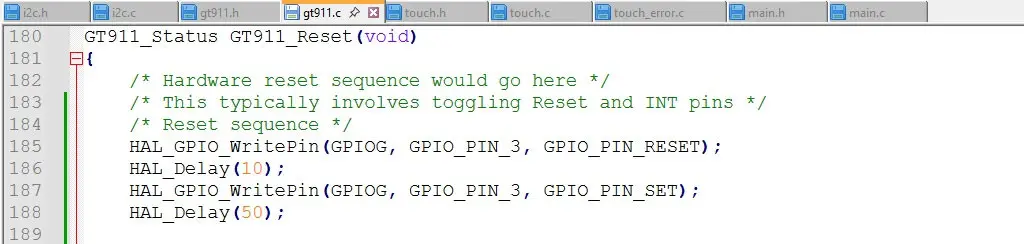
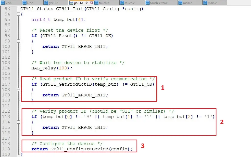
The GT911 is then initialized through a specific reset sequence. The sequence involves toggling the RESET pin, holding the INT pin low, and finally releasing it after bringing the RESET pin high. A wait time of 100 milliseconds ensures the controller has enough time to initialize.
Communication is verified by reading the Product ID (1) from the GT911’s registers using its I2C address. A successful read operation (2 and 3) confirms that the device is properly initialized.
The GT911’s configuration registers, starting at address 0x8047, allow fine-tuning of the touch controller’s behavior. The configuration process begins with preparing the required settings. Key parameters include the number of touch points (set to five), touch threshold, X and Y resolution (480×800), interrupt trigger mode, and refresh rate (set to 5 milliseconds). These values are written to the configuration registers sequentially.

Several registers must be configured at initialization to function properly. Some of the key parameters are:
| Register | Name | Value | Description |
| 0x8047 | X Output Max | 0x01E0 | Horizontal Resolution (480) |
| 0x8049 | Y Output Max | 0x0320 | Vertical Resolution (800) |
| 0x804B | Touch Points | 0x05 | Maximum Number of Touch Points |
| 0x8057 | Module Switch 1 | 0x14 | Enable Interrupt Trigger on Touch |
| 0x805D | Refresh Rate | 0x05 | Touch Data Refresh Rate (5ms) |
Once the configuration data is written, it is saved to non-volatile memory by writing to the specific control register located at 0x8040. Writing a value of 0x01 to this register ensures that the configuration is stored and will persist across power cycles and resets. After saving the configuration, it is necessary to write 0x80 to the same control register at 0x8040. This step transitions the GT911 from configuration mode to application (operation) mode, enabling it to process touch data.
Touch data is continuously updated in the GT911’s memory space, beginning at address 0x814E. The system can either poll these addresses periodically or rely on the interrupt mechanism to read the data only when a touch event occurs. The data includes details about the number of touch points, their coordinates, and other relevant attributes.
Touch Events
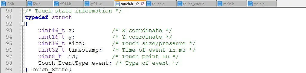
Data Structure of Touch Events
The GT911 stores touch event data in its memory, starting at address 0x814E. The structure of the touch data includes the following key fields:
- Status Byte: This byte indicates the number of touch points detected and the status of the touch data.
- Touch Point Data: For each detected touch point, the data includes:
- X-coordinate (2 bytes): The horizontal position of the touch point.
- Y-coordinate (2 bytes): The vertical position of the touch point.
- Touch ID: An identifier for the touch point, allowing tracking of individual touches.
- Touch Event: The type of event, such as touch down, lift off, or move.
Each touch point’s data is arranged sequentially in the memory block.
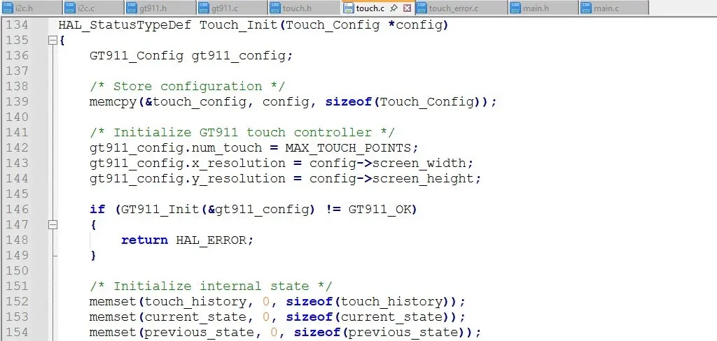
Touch Initialization
Initialization of the touch interface provides some of the configuration data to be stored in the GT911 configuration structure. The maximum number of touch points and the resolution of the touch panel are the data stored in the config structure. Then the history, current state, and previous state arrays are set to zero.
Reading Touch Data
Check for interrupts if the INT pin is configured, as the interrupt signal indicates new touch data is available. To simplify the code for this application note, polling is used to check for updates. Read the status byte at address 0x814E first to determine if new touch data is available. This byte also specifies the number of touch points (ranging from 0 to 5).
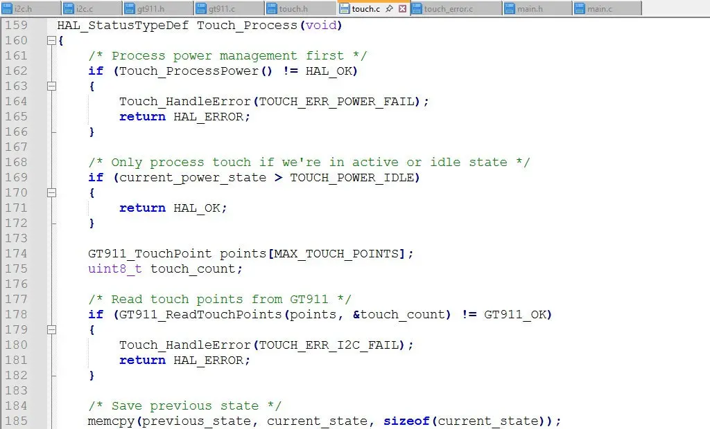
Figure 11: Reading the Touch Events from Touch_Process()
If the status byte indicates new data, the subsequent touch point information is read from the GT911’s memory. Each touch point occupies a fixed number of bytes, and the data is extracted for all active touch points. After reading the touch data, the status byte must be cleared by writing 0x00 back to address 0x814E. This step notifies the controller that the data has been processed and prevents duplicate readings. This is handled from Touch_Process() by calling Process_TouchEvents().

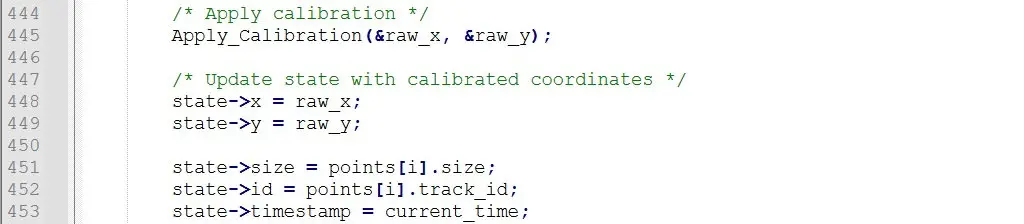
Processing Touch Events
The touch data is then retrieved, and it must be processed to get the information for the application. As a first step the touch ID should be retrieved. The touch ID helps differentiate between multiple touch points, allowing the system to track individual touches as they move or lift off. Then the touch event must be interpreted.

Mapping the coordinates is the next step in the process. The raw X and Y coordinates are scaled to the resolution of the touch panel (e.g., 480×800) to align with the application’s display requirements.
The event type for each touch point is analyzed to determine the action. For example:
- Touch Down: A new touch point has been detected.
- Touch Move: An existing touch point has changed its position.
- Touch Lift Off: A touch point has been released.
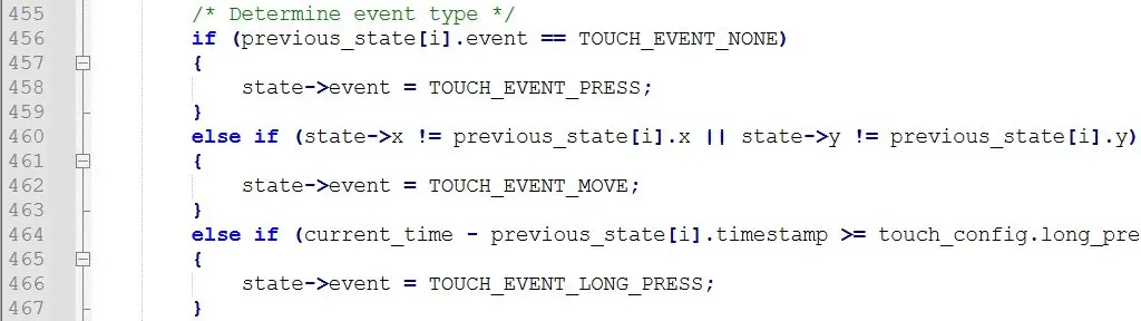
The release or lift off event is processed separately.
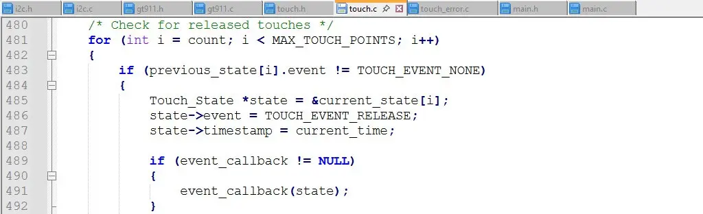
Based on the touch data, application-specific actions are executed. This might include updating a graphical user interface, triggering events, or controlling devices. The processing of the touch events is handled in the callback function located in the main.c file.
Optimization Considerations
Efficient handling of touch events is critical to maintaining responsiveness in the application. Using the INT pin to signal new data reduces the need for constant polling, conserving processing resources. Then retrieve all touch point data in a single I2C transaction to minimize communication overhead. Implement debouncing logic to filter out noise and spurious touch events, improving accuracy. There is some debouncing logic already part of the GT911 controller. This is where the filtering registers are utilized. When possible, ensure the touch data is processed within the required refresh period (e.g., 5 milliseconds) to maintain a smooth user experience.
Gesture Recognition
The GT911 uses its integrated gesture engine to analyze touch data patterns in real-time. By tracking the movement and position of one or more touch points, the controller identifies predefined gestures. These gestures are mapped to specific codes, which are then stored in a dedicated register for retrieval by the host system.
The commonly supported gestures include swipe gestures (up, down, left, and right), zoom gestures (pinch-in and pinch-out), long press, and double tap. The gesture recognition process reduces the computational burden on the host system by offloading pattern analysis to the GT911.
Configuring the GT911 for Gesture Recognition
Gesture detection is enabled by writing to the gesture enable register, typically located in the configuration block of the GT911’s memory. The specific address and value depend on the desired gesture set. Adjust gesture-specific parameters such as sensitivity, speed thresholds, and movement ranges. These parameters ensure accurate recognition based on the application’s requirements and display size.
After updating the gesture settings, write 0x01 to the control register at address 0x8040 to save the configuration. Transition the GT911 to application mode by writing 0x80 to the same register.
Verify that gestures are detected correctly by reading gesture event data from the dedicated register after performing gestures on the touch panel.
Processing Gesture Events
The GT911 stores gesture event information at address 0x814F. This register contains the gesture code, which corresponds to the detected gesture.
The code breaks up the gesture processing into several functions. If the gesture feature of the GT911 is enabled in the firmware, then the initial processing is performed in the Touch_Process() function.
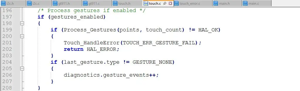
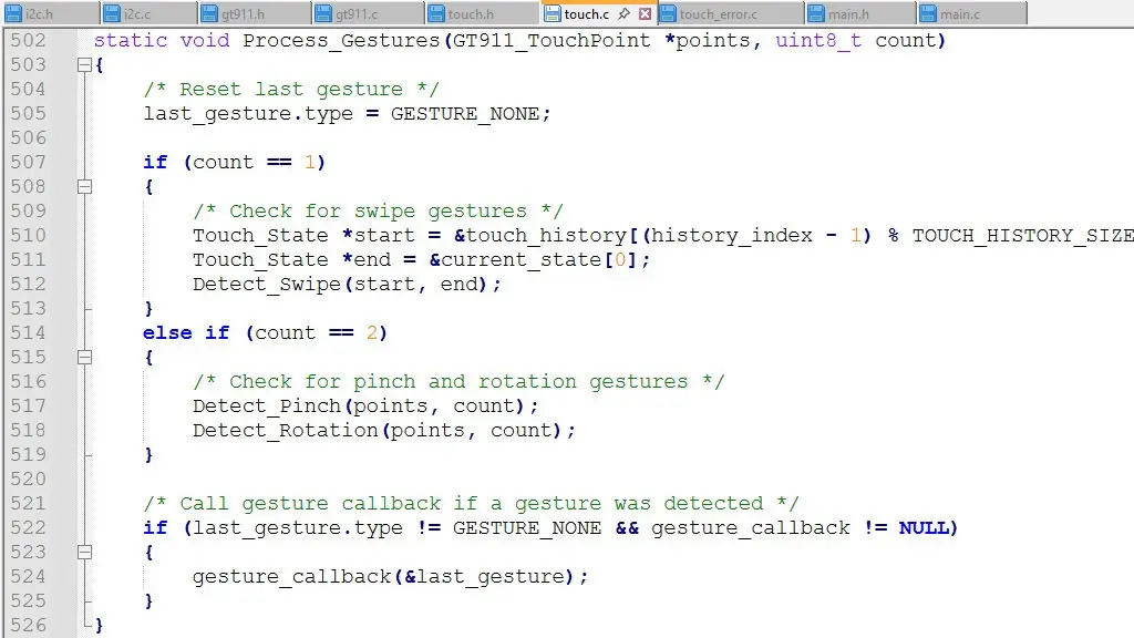
Once the gesture event has been captured, the event is processed in the Process_Gestures() function. The gesture code is retrieved from the gesture register. This code uniquely identifies the type of gesture detected (e.g., swipe left, zoom in).

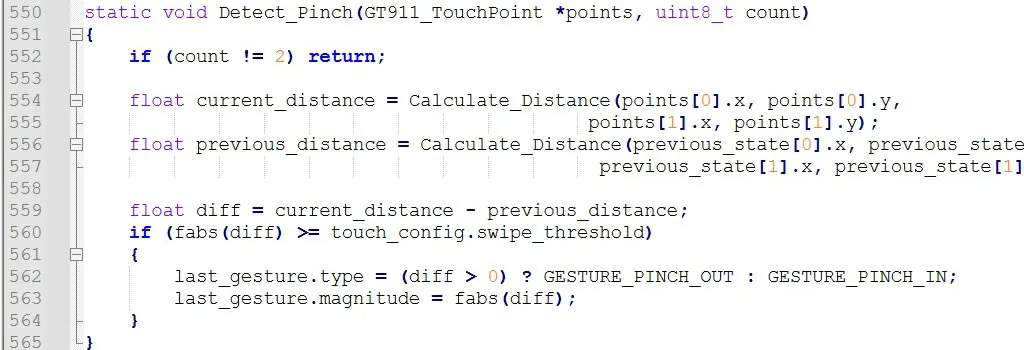
Additional processing is called to handle the pinch, rotation, and swipe gestures.

After reading the gesture code, clear the register by writing 0x00 to prevent duplicate event processing.
Now the gesture codes need to be mapped to actions. Use a lookup table or conditional logic in the application firmware to map gesture codes to specific actions. In the code presented, a gesture callback is used to call the handler function. This handler function is in main.c at the application level. It currently uses printf() to output a message indicating the gesture. It is left to the end user to adapt the code to their application.
Gesture Mode vs. Touch Mode
The GT911 does not support gesture mode and touch mode simultaneously. When gesture mode is enabled, the touch controller focuses on detecting predefined gesture patterns, and regular touch point data (such as X and Y coordinates or multi-touch information) is not actively processed or reported. Conversely, in touch mode, the GT911 operates as a multi-touch controller, providing detailed touch data but not performing gesture recognition.
The GT911 operates either in gesture mode or touch mode based on the configuration settings. You need to decide which mode is more critical for your application.
To switch between modes, you need to reconfigure the controller and restart it appropriately. This involves writing the relevant configuration values to enable or disable gesture mode and saving the settings using the control register. Switching modes during runtime is possible but may introduce latency due to the reconfiguration process.
If your application requires both functionalities, consider designing it to toggle between modes based on user context. For instance, gesture mode could be used for specific interfaces, while touch mode is active during detailed user interactions. Another approach is to offload gesture recognition to the application software using raw touch data from touch mode, although this requires additional processing and development effort.
Optimizing Gesture Handling
To enhance responsiveness and accuracy, several steps can be taken. Fine-tune the sensitivity parameters during configuration to match the display size and user interaction patterns. Implement debouncing logic to avoid false positives or unintentional gesture detection. Ensure gesture data is processed promptly to deliver a seamless user experience. During development, log the gesture codes to validate detection accuracy and refine configuration settings.
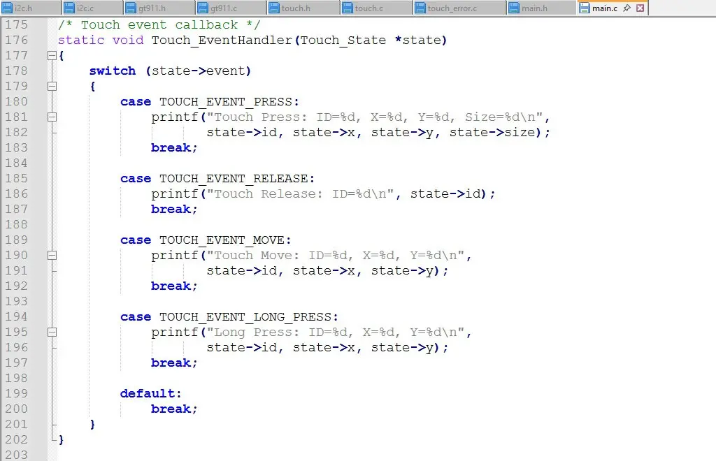
Application Integration
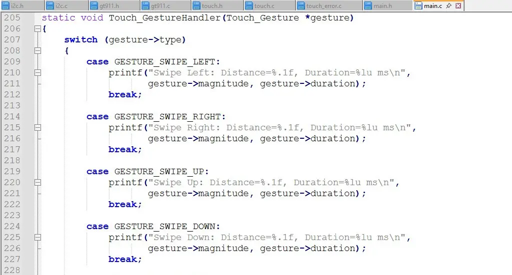
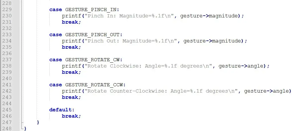
The touch event handling can be integrated into the main application loop or through interrupt-driven mechanisms. The Touch_EventHandler() and Touch_GestureHandler() functions are implemented to process the touch events but only use printf() to output a message about the event. The end user will need to add functional code according to the specific application requirements.
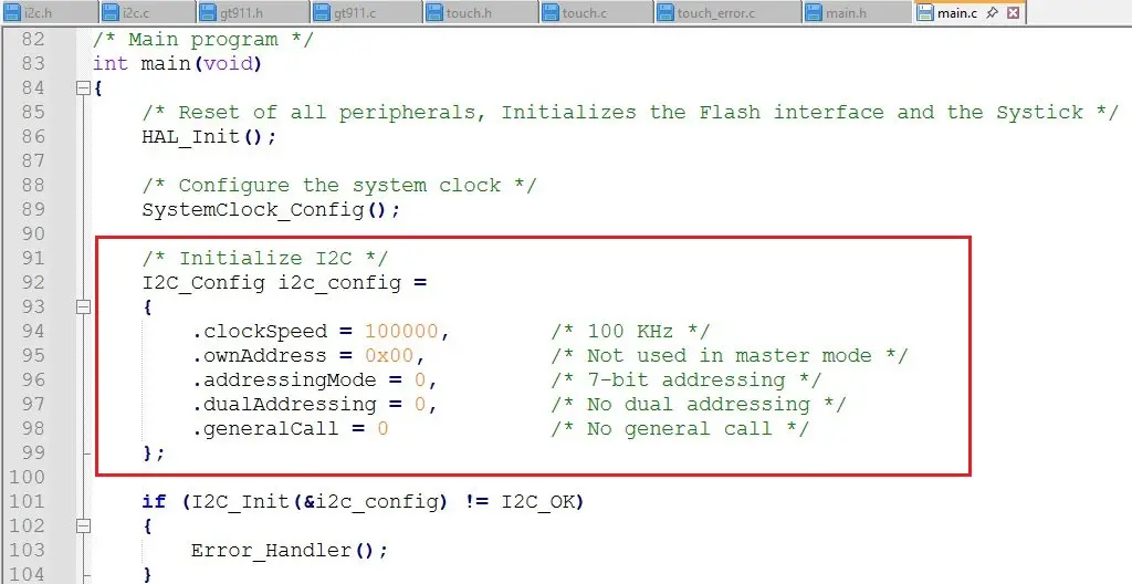
The main application configures the I2C peripheral at the beginning of main().
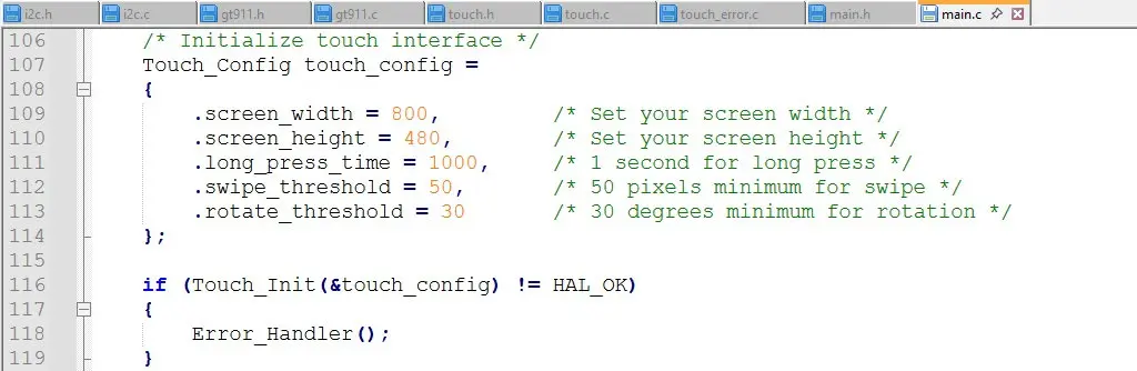
Then the touch interface can be initialized.
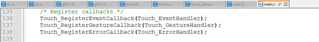
Next, the callback events need to register the event handlers.
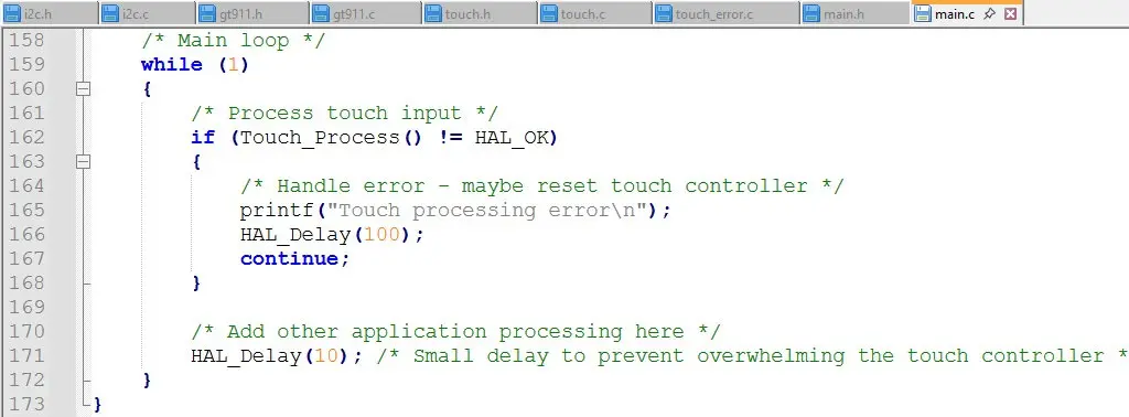
The last step in getting the touch interface application code running is the main while loop. All the other code developed for the application makes the final while loop simple to implement. Here is what it looks like:
Conclusion
Using the I2C4 peripheral on the STM32H747I-DISCO, the GT911 touch controller can be successfully configured to detect touches on the Focus LCDs E43GB-I-MW405-C display. This application note provided the steps required to program the STM32H747I-DISCO to control the GT911 touch controller. It walked through the configuration of the I2C peripheral, the low-level device driver for the GT911, and the higher-level touch interface code used by the application code.
Recommended Next Steps
In the source code that can be provided by Focus LCDs, power management, error handling, and diagnostic functions have been included. This code is currently limited to basic functionality and more robust functions are left to the end user. It is included as a template on how to implement the functions.
Basic touch panel calibration routines have been implemented in code but are not used in the application layer. It is up to the end user to add this functionality into the main application.
Additional Information
The source code for the GT911 Capacitive Touch Controller can be acquired by contacting Focus LCDs.
LCD Handling Precautions
- Do not store the TFT-LCD module in direct sunlight, best stored in a dark place.
- Do not leave it exposed to high temperature and high humidity for a long period of time.
- Recommended temperature range is 0 to 35 °C, relative humidity should be less than 70%.
- Stored modules away from condensation as formation of dewdrops may cause an abnormal operation or failure of the module.
- Protect the module from static discharge.
- Do not press or scratch the surface and protect it from physical shock or any force.
Disclaimer
Buyers and others who are developing systems that incorporate FocusLCDs products (collectively, “Designers”) understand and agree that Designers remain responsible for using their independent analysis, evaluation, and judgment in designing their applications and that Designers have full and exclusive responsibility to assure the safety of Designers’ applications and compliance of their applications (and of all FocusLCDs products used in or for Designers’ applications) with all applicable regulations, laws, and other applicable requirements.
Designer represents that, with respect to their applications, Designer has all the necessary expertise to create and implement safeguards that:
(1) anticipate dangerous consequences of failures
(2) monitor failures and their consequences, and
(3) lessen the likelihood of failures that might cause harm and take appropriate actions.
The designer agrees that prior to using or distributing any applications that include FocusLCDs products, the Designer will thoroughly test such applications and the functionality of such FocusLCDs products as used in such applications.

