There are multiple interface options available for transmitting data to a display. One of the most common is the parallel interface. There are two categories of parallel interfaces, MCU and RGB. The MCU interface
can be used on a variety of displays while RGB is only found on TFT’s. The interfaces differ in their control
signals, number of pins, timing and memory allocation. Below is a review of each of these interfaces.
RGB
The RGB interface is a special parallel interface that transmits up to 8-bits of red, green and blue data to each pixel. The number of bits transmitted per clock cycle is dependent on the setup and programming of the display. It can vary from 16 to 18 or 24 data pins that are used for each of the RGB signals. RGB does not typically have internal DDRAM memory and the data is written directly to the device from the GPIO pins. This allows for RGB is transmit data faster than the MCU interface at the cost of using more data pins. The RGB interface is typically chosen for displaying videos.
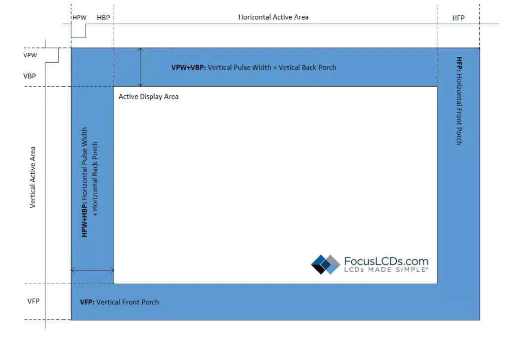
The number of bits transmitted effects the color depth of the display. For example, a 16-bit RGB interface would have 5 red, 6 green, and 5 blue data bits/pixel. This results in a 65k color depth ( 2^16 = 65k colors). The RGB interface typically sends the 16-bit data over the 16 data pins in one HSYNC pulse.
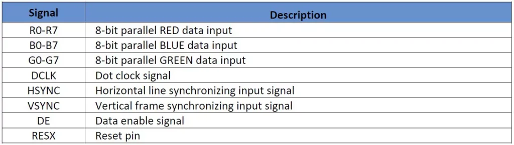
It is important to note that the number of data lines is not always proportional to color depth. For example, a 6-bit (6-line) RGB interface can be chosen to display 565-RGB colors over 3 clock pulses rather than all at one. The RGB interface also needs the control signals SYNC, VSYNC, DCLK, and DE to indicate where and when the RGB data should be displayd. Below is an example of the pin descriptions for a 24-bit RGB interface.
MCU (8080 and 6800)
The MCU interface has two standard types, the Intel-8080 and Motorolla-6800 series. These interfaces communicate through read, write and chip-select signals to address registers or display RAM. The slight difference between the two pertains to the direction and separation of the write and read signals.
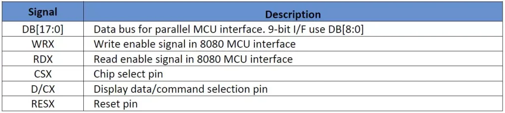
The MCU interface can read and write data to internal memory. This interface would be chosen to display images from memory. The MCU parallel interface sends RGB signals over 8, 9, 16 or 18-bit data lines. Below are the pin descriptions on a 9-bit 8080 parallel MCU interface.
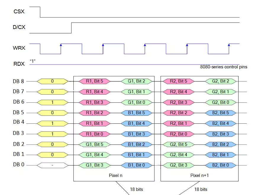
Like the RGB interface, color mapping of the RGB signals is done to assign bits/pixel over the selected data lines. To further elaborate, a 9-bit 8080-series MPU interface can be directed to send RGB 6-6-6 bits/pixel (262k color-depth) over 9-data lines in two write cycles. Below is the timing diagram that shows the color mapping of each pixel.
Deciding between the MCU and RGB interface depends on intended application of the display. Each interface places different demands on the processor and memory available. Other factors such as pin availability and processing speed need to be considered when choosing an interface. RGB can be used in high performance applications but requires more pins and needs higher processing speed and memory allocation. Parallel MCU can be a great option for displaying images as it can store memory in its’ internal frame buffer. The MCU interface is a simpler interface to command than RGB as timing requirements are not as demanding.
DISCLAIMER
Buyers and others who are developing systems that incorporate FocusLCDs products (collectively, “Designers”) understand and agree that Designers remain responsible for using their independent analysis, evaluation and judgment in designing their applications and that Designers have full and exclusive responsibility to assure the safety of Designers’ applications and compliance of their applications (and of all FocusLCDs products used in or for Designers’ applications) with all applicable regulations, laws and other applicable requirements.
Designer represents that, with respect to their applications, Designer has all the necessary expertise to create and implement safeguards that:
(1) anticipate dangerous consequences of failures
(2) monitor failures and their consequences, and
(3) lessen the likelihood of failures that might cause harm and take appropriate actions.
Designer agrees that prior to using or distributing any applications that include FocusLCDs products, Designer will thoroughly test such applications and the functionality of such FocusLCDs products as used in such applications.

