Application Note FAN9203
This application note shows how to dim the backlight using Pulse Width Modulation controlled through code rather than manually variating voltage levels.
1. Introduction
With the growing popularity of easy-to-use hardware such as the Arduino1 or Raspberry Pi2, it is easier to build systems. In this application note, a simple display project is shown wherein the backlight is dimmed from 100% to 0%. It features the C164AXBSYLY6WT character display module (datasheet):
- 16 pins, 87.0 mm x 60.0 mm
- 16×4 display, STN
- ST7066U Driver IC
- Yellow background
- Yellow or green backlight
- Wide temperature (-20ºC to +70ºC)
- Positive transreflective
- Bottom viewing angle (6 ‘O Clock)
- ROHS-compliant
STN (Super-twisted Nematic) provides a sharper image and wider viewing angle than TN (Twisted Nematic). The cost for STN if approximately 5% higher than TN. STN is an ideal fluid for outdoor products that need to be read at various angles.
The Transflective polarizer is a mixture of Reflective and Transmissive. It provides the ability to read the LCD with or without the backlight on. It will work for all lighting conditions from dark with backlight to direct sunlight which makes it the most common choice. There is no cost difference between Transflective, Transmissive and Reflective polarization.
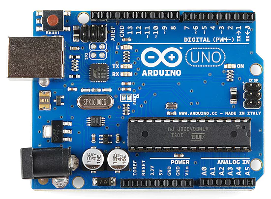
Figure 1: Arduino UNO
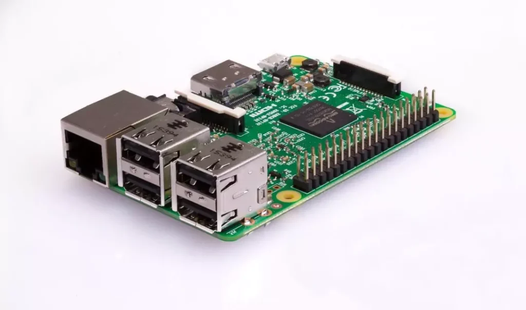
Figure 2: Raspberry Pi
2. What You Need
| Qty | Description | Store |
| 1 | Arduino UNO (Rev 3) with USB Cable | Arduino |
| 1 | C164AXBSYLY6WT Character Display Module | FocusLCDs |
| 1 | Solderless Breadboard | Adafruit |
| 1 | Male-to-Male Jumper Wires (Set) | Adafruit |
| 1 | 10kΩ Potentiometer (Small) | Adafruit |
| 1 | Arduino IDE | Arduino |
3. Instructions
3.a Download and install the Arduino IDE (Integrated Development Environment). Or you can use the cloud-based version: “Arduino Web Editor”.
3.b Wire up the circuit as shown in the following schematic (Figure 3). It should look similar to Figure 4. Note that Arduino pins 4 to 9 are digital I/O pins. Arduino boards also have analog I/O pins. Connect the Arduino to a PC via the USB cable.
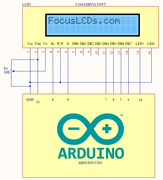
Figure 3: LCD and Arduino UNO Schematic
The LCD is powered from the Arduino (+5V) through its USB port. LCD contrast is varied via potentiometer R1 through pin VO. Reset (RS), Enable (E), DB4 to DB7 is controlled via the sketch. While R/W is grounded (logic LOW); this means that the program is writing to the LCD register. If it is a logic HIGH, then it is reading from the LCD register. LED+ is connected to pin 10 of the Arduino which functions as a PWM.

Figure 4: Wiring of Arduino to LCD.
3.c Open this Arduino program (AKA Sketch): PWM-Dimming.ino.

Figure 5: Arduino IDE and sketch.
The programming language used in the Arduino IDE is a derivative of C and C++ programming languages. At the heart of this sketch is LiquidCrystal library which is installed by default with the IDE. It is based on the HDD44780 LCD driver and is compatible with ST7066U.
In line 32 of the sketch, the library is initialized by associating the LCD pin to the Arduino pin it is connected to like so:
const int rs = 8, en = 9, d4 = 7, d5 = 6, d6 = 5, d7 = 4;
LiquidCrystal lcd(rs, en, d4, d5, d6, d7);
Note that only 4 bits are needed to use the LCD (DB4 to DB7).
3.d Specify Arduino UNO is used and select the correct PC COM port. In the IDE top menu, select Tools > “Board: Arduino / Genuino UNO”. Then again, Tools > Port.
Upload and run the sketch. The LCD should have a display like in Figure 6.

Figure 6: Sketch running on the Arduino.
4. Summary
The brightness is controlled by line 55 of the sketch. There are 256 levels of brightness corresponding to the PWM duty cycle (0-100%). 0% or 0 means no backlight while 100% or 255 is full backlight.
In this example, we initially print some text to the LCD (lines 39-46). The brightness is first set to 100% (i.e. 255). Then decrement in 10% (i.e. 25.5) steps with a delay of 3 seconds between each step so you can see the effect (line 56-59).
A typical application of this method is in mobile devices where the backlight is dimmed according to ambient lighting.
It is worth noting that Arduino PWMs typically have a frequency of 490 Hz which is more than enough to prevent flicker. The suggested range is 60 to 250Hz. There is an available library where the frequency can be controlled (download here).
Lastly, pay attention to the initialization of the LCD library specifically the wiring of the Arduino pin with the corresponding LCD pin. Incorrect declaration of the pins may result in a malfunction. If RS is connected to 9 and EN is connected to pin 8 of the Arduino, the initialization is:
LiquidCrystal lcd(9, 8, 7, 6, 5, 4);
DISCLAIMER
Buyers and others who are developing systems that incorporate Focus LCDs products (collectively, “Designers”) understand and agree that Designers remain responsible for using their independent analysis, evaluation and judgment in designing their applications and that Designers have full and exclusive responsibility to assure the safety of Designers’ applications and compliance of their applications (and of all Focus LCDs products used in or for Designers’ applications) with all applicable regulations, laws and other applicable requirements.
Designer represents that, with respect to their applications, Designer has all the necessary expertise to create and implement safeguards that:
(1) anticipate dangerous consequences of failures
(2) monitor failures and their consequences, and
(3) lessen the likelihood of failures that might cause harm and take appropriate actions.
Designer agrees that prior to using or distributing any applications that include Focus LCDs products, Designer will thoroughly test such applications and the functionality of such Focus LCDs products as used in such applications.
1Arduino is an open-source development platform for easily building electronics projects that can electrically sense and control other objects. Arduino boards are primarily based on the Atmel AVR (8-bit) microcontroller (Example: Arduino UNO).
2The Raspberry Pi is a single-board computer. It features the Broadcom SOC (System-on-Chip) which includes a CPU and a GPU. Similar to the Arduino, it can be used for electronics projects (professional or hobbyist).

