Break Down of a parallel interface

This article about the parallel interface was provided by Paul Hay, Electrical Engineer.
LCD Displays that use a parallel interface include Character, Graphic and TFT.
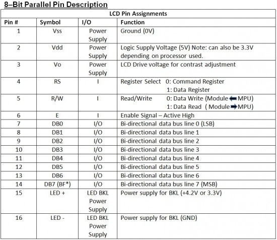
LCD controllers use common interfaces for user interaction. The initial step is to energize the LCD. Reads and Writes are sent via 8 data lines and 3 control lines. These control lines are Read/Write (R/W), Enable (E) and Register Select (RS).
What does each pin represent?
Vo – Contrast Adjustment. This adjusts the voltage being applied to the LCD. A potentiometer or a software controlled solution can be used to adjust the contrast of the LCD panel.
RS – The Register Select signal determines if the Data Bit values are interpreted as a command or data. In other words is a there a character ready to display or is it a command giving the LCD module an instruction.
R/W – When R/W is high the function is a data Read. When R/W is low (ground) the function is a data Write.
E – The enable pin, is the command/data latching signal for the LCD. The LCD will latch in whatever is on the Data bus and then process it on the falling edge of the E signal. When this signal is low, the LCD does not care what is happening on the R/W, RS and the data bus lines; when this signal is set to logical high, the LCD is processing the incoming data.
How to determine if busy when in Read/Write mode
When using the LCD in Read and Write mode, the DB7 (Data bit seven) pin is the busy flag (BF). When DB7 is clear (low state or 0V), the LCD is ready for the next command.
Data and commands are read in on the falling edge of the E signal.

4 BIT PARALLEL MODE
For the parallel interface, it is possible to use the LCD in 4-Bit mode. For this 4 data lines are used. Only data lines DB4-DB7 are active. Instead of sending data in Bytes, data is sent in Nibbles instead. The drawback is this will take more time. The benefit is now 4 lines from a Microcontroller can be used for other purposes. A good flow chart and example code can be found at http://www.embeddedcraft.org/lcd4bit.html.
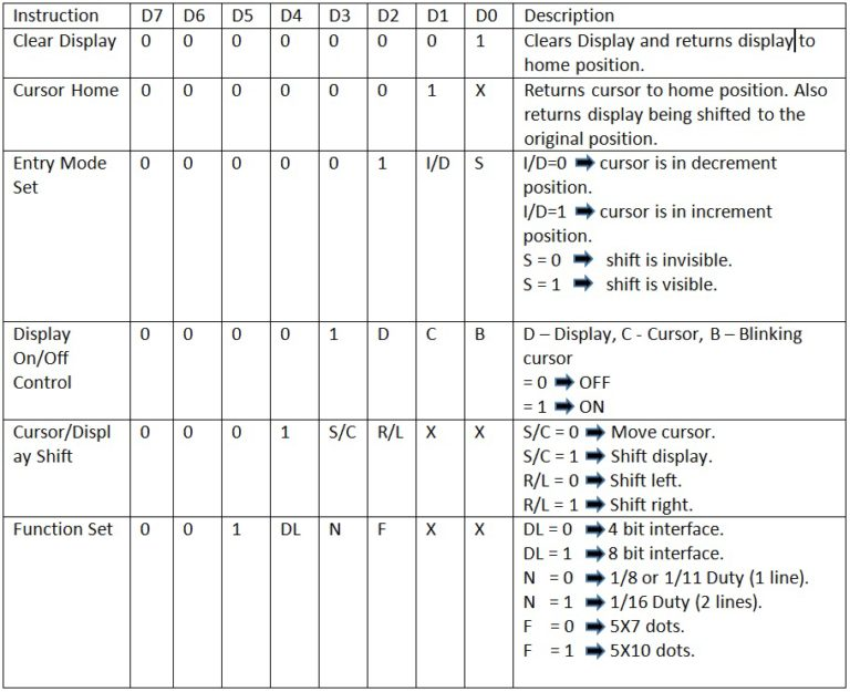
Setting Control Words
The following table shows how control words are set. When RS=0 and R/W=0, data in the pins DB0-DB7 will have the following meaning:

Parallel Interface Duty Cycle Explained
Each pixel or segment of an LCD is turned on (energized) by an AC voltage being applied to it. In the simplest case each segment is directly being driven by the LCD controller. In the example of a 20 X 4 display, 3200 connections would be necessary! Since this is not a reasonable or prudent use of board space, not to mention routing issues, multiplexing is used. With multiplexing each segment is being driven ½ of the time, 1/32 of the time, 1/64 etc. This is similar to how a fluorescent light bulb is actually turned on and off by AC current, but at that frequency the flicker isn’t usually detected by the human eye. A higher duty cycle will give the sharpest image with direct driven(the power is on 100% of the time) being the best.

Parallel interface: SPI and I2C
PRO SPI:
SPI (Serial Peripheral Interface) has a simpler bus protocol than I2C (Inter-Integrated Circuit) which usually requires a software stack to control the protocol. SPI can achieve faster speeds and be used over longer ranges. SPI is also full duplex compared to half-duplex for I2C. SPI uses SSEL/CS lines, because of this multiple chips of the same kind that can be connected. For CSI there is a limited amount of addresses combinations available and address conflicts are more common.
PRO I2C:
I2C has fewer connections. SDA is used for data while SDC is used for clocking. Because I2C uses chip addresses there is no need for the additional SSEL and CS lines. Also there is no need to track exactly which SSEL and CS lines go to which devices. Because I2C uses an open collector bus there is some flexibility to the voltages which can be used (3.3V or 5V). In I2C mode it is possible for multiple devices on the bus to be the master. It is also possible for a device to switch between master and slave if supported. On SPI, the wiring determines which is master and which is slave.