Need a more in depth explanation? See our latest resource explaining LCD voltage inputs.
This article about LCD voltage inputs was provided by: Paul Hay, Electrical Engineer.
VCC, VDD, VSS, VEE, V0 Explained
Monochrome character, graphic and static displays require different input voltages. All the different LCD voltage symbols can be confusing, but believe it or not, there is a system to the madness.
LCD Voltage: the basics of LCD power inputs
The voltages VCC, VDD, VSS and VEE are used in describing voltages at various common power supply terminals. The differences between these voltages stem from their origins in the transistor circuits they were originally used for.

This LCD voltage terminology originated from the terminals of each type of transistor and their common connections in logic circuits. In other words, VCC is often applied to BJT (Bipolar Junction Transistor) collectors, VEE to BJT emitters, VDD to FET (Field-Effect Transistor) drains and VSS to FET sources. Most CMOS (Complementary metal–oxide–semiconductor) IC data sheets now use VCC and GND to designate the positive and negative supply pins.
In general VCC and VDD are used for positive voltage, and VSS and VEE are for ground.
LCD Displays: What do the C, D, S and E stand for?
In the Pleistocene era (1960’s or earlier), logic was implemented with bipolar transistors. NPN (Negative-Positive-Negative) were used because they were faster. It made sense to call positive supply voltage VCC where the “C” stands for collector. The negative supply was called VEE where “E” stands for emitter.
When FET transistor logic came around a similar naming convention was used, but now positive supply was VDD where “D” stands for drain. The negative supply was called VSS where “S” stands for source. Now that CMOS is the most common logic this makes no sense. The “C” in CMOS is for “complementary” but the naming convention still persists. In practice today VCC/VDD means positive power supply voltage and VEE/VSS is for negative supply or ground.

Why VDD and not simply VD?
The convention of VAB means the voltage potential between VA and VB. The convention of using 3 letters was used to show power supply and ground reference voltages as well. In some cases a processor may have both an analog and digital power supply. In this case VCCA/VCCD and VSSA/VSSD are used. Another reason for the 3 letters is in an NPN circuit with a load resister between the collector and VCC. VC would be the collector voltage. In this case VCC is the positive power supply voltage and would be higher than VC.
EXAMPLES OF LCDS THAT USE THIS NOMENCLATURE:
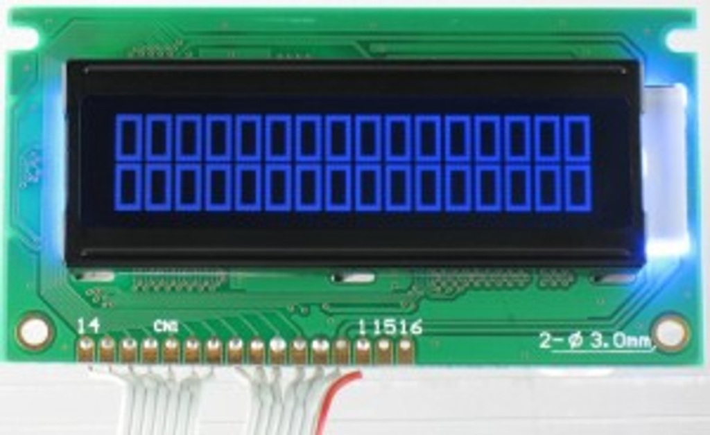
Below is the data sheet for a character LCD Display:

Pin one is called out as VSS which is also GND. Pin two is VDD, or the positive power.
Note: Most Segment, Character and Graphic displays will operate with a VDD of 5V or 3.3V. It may be possible to drive the display with as little as 3.0V, but the module may not perform very well in colder temperatures. The colder the ambient temperature, the more power is required to drive the segments.
Pin three (3) is Vo and is the difference in voltage between VDD and VSS. This LCD voltage is adjusted to provide the sharpest contrast. The adjustment can be accomplished through a fixed resistor or a variable potentiometer. Many products have firmware that monitor the temperature and automatically adjust the contrast voltage.
What is V0 on an LCD?
In a Liquid Crystal Display (LCD), V0 is used to vary the screen brightness or contrast. Contrast, simply put is the ratio of the light areas to the dark areas in a LCD. This is usually done in a production setting with values which are optimized for most users. Temperature can have an undesirable effect on the display brightness and for this reason a varying resister or potentiometer is used to accommodate the desires of the user.
Below is a data sheet of a 16×2 Character LCD module that shows various recommended driving voltages. The LCD voltage can range from MIN (minimum) to TYP (Typical) to Max (maximum).
Note: the colder the temperature, the higher the LCD voltage.

What happens if the LCD driving voltage is too low?
If the supplied LCD voltage drops too low, the display is ‘under-driven’ and will produce segments that are ‘grey’. The lower the LCD voltage falls below the acceptable threshold, the lower the contrast will be.
What happens if the LCD driving voltage is too high?
If the LCD is over-driven, you may see ghosting. This is where segments that should not be ‘on’ are gray. They are not as dark as the segments that should be on, but they can be seen and may cause confusion for the end user.
Power connections for a custom LCD display
There are times when a customer needs to replace a display that has been discontinued or EOL (End-Of -Life) by their previous LCD supplier. The previous LCD’s pin-outs may be different than Focus’ standard, off-the-shelf display. This is not a large problem to overcome.
Focus Displays will redesign the PCB to match the customer’s old pin out. This will save the customer time and cost so that they will not need to redesign their PCB.
LED Backlight power connections
LED backlights are DC (Direct Current) driven and can be supplied from any one of three locations. The most popular is from pins 15 and 16. The second most popular option is to draw power from the ‘A’ and ‘K’ connections on the right side of the PCB.
The third option is to pull power from pins one and two. This is the same location from which the LCD is pulling its power. Focus does not recommend this option and can modify the PCB for the customer to connect the backlight from a different location.
LCD voltage inputs and charge pumps
Many LCD Modules will require more than one internal voltage/current. This may make it necessary for the customer to supply the needed inputs. They may need to supply 3V, 5V, 9V, -12V etc.
The solution for this is to integrate a charge pump (or booster circuit) into the LCD circuitry. This solution works in most applications, but if the product will be operating in an intrinsic environment, care must be taken with layout of the circuit board.
Intrinsically-safe LCDs are Liquid Crystal Displays that are designed to operate in conditions where an arc or spark can cause an explosion. In these cases, charge pumps cannot be employed. In fact, the total capacitive value of the display needs to be kept to a minimum.
Focus Display Solutions does not build a display that is labeled ‘Intrinsically safe’ but we do design the LCD to meet the requirements of the engineer. In meeting the design engineer’s requirements, the display may need to contain two or three independent inputs. Focus can redesign the PCB and lay out the traces to allow for these additional inputs.

Has your LCD display been discontinued or obsolete? Do you require a new supplier?
Focus Display Solutions is able to reverse engineer and develop an equivalent LCD Display.


