
One of the advantages of designing a custom display is the ability to reduce your LCD display’s thickness by selecting a thin ITO glass; which is key to a thin LCD module.
Additional advantages to customizing segment displays include reduced unit cost, small tooling NRE (Non-recurring engineering) investment and low power consumption.
An introduction to Liquid Crystal Displays
Liquid Crystal Displays (LCDs) use a nematic fluid to generate different letters, numbers and icons through the use of an electrical field.
Other display technologies provided by Focus Display Solutions are… Thin Film Transistor (TFTs), Vacuum Fluorescent Displays (VFDs) and Light Emitting Diodes (LEDs) do not use any type of fluid.
Construction of a LCD:
The structure of the LCD is very basic, but a special glass called ITO glass is used in constructing the display. Three sides of the ITO glass are glued together with an adhesive or epoxy. Both the ITO glass and the nematic fluid used are transparent. There is a small gap of one or two millimeters between the top and bottom layer of glass. A nematic fluid is then injected between the layers. Finally, a cap is placed on the fourth side to keep the fluid from leaking out.
A polarizer is applied on both the top and bottom layer of glass. The polarizer on the top layer is always Transmissive, whereas the bottom layer can be Reflective, Transflective or Transmissive. For more details on the different types of polarizers, please read our article: LCD Polarizers.

What is ITO glass?
Indium Tin Oxide (ITO), also referred to as tin-doped indium oxide, is a standard piece of transparent glass with a conductive film applied to the surface. The job of the conductive film is to control the behavior of the nematic fluid when energized by an electrical field. ITO glass is used on all segment, character and monochrome graphic displays.
ITO glass can be cut to custom dimensions, but smaller sized glass can add a significant cost increase to the overall cost of the LCD. The reason for the increased cost is the amount of labor and time required to add a polarizer to the small piece of glass.
Thin ITO glass: key to your thin LCD module
Many times customers require the display to be as thin as possible; one method to achieve a thin LCD module is to select a thinner ITO glass. Keep in mind that the thinner the glass, the more expensive and the higher the fallout rate.
Note: Fallout rate does not mean failures of the LCD’s in the field; fallout is when the display fails on the manufacturing line. If the display fails in production, it is discarded before it is shipped to the customer. Once the display passes QA (Quality Assurance) it will operate normally for the life of the product.
There are four thicknesses of ITO glass.
- 0.40 mm (Most expensive)
- 0.55 mm
- 0.70 mm
- 1.1mm (Least expensive)
The following chart shows available ITO sizes and combined thickness of the LCD.

Below is a cad drawing showing the side view of a segmented display using .70 mm thick ITO glass. The overall thickness of the LCD is 2.00mm max.

Note: The top piece of glass is smaller than the bottom piece of glass allowing for pin placement. This same design is also used for displays that use zebra or elastomeric contacts.
Adding a custom backlight to your monochrome LCD and keeping it thin
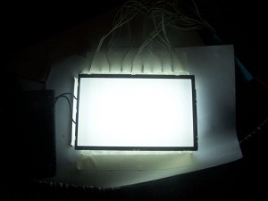
It is possible to add a backlight to the monochrome display to make the display readable in low or no light conditions. The challenge of adding a LED backlight is that it increases the thickness of the LCD by as much as 5mm to 9mm.

In the photo above, a segmented LCD is combined with a LED backlight and backlight diffuser. A printed circuit board (PCB) is used to hold the assembly together. As the backlights name suggests, a light is placed behind the bottom layer of ITO glass.
Note: A backlight diffuser’s job function is similar to the lamp shade used on a table lamp. It disperses the light from each led to provide a more uniform appearance. Without the diffuser, there would be hot and cold spots on the display. A hot spot is where the backlight is too close to the LCD glass and it is overly bright; the area around the hot spot is dimmer and is referred to as a ‘cold spot’.
If the backlight needs to be brighter while keeping an even flow of light, it is possible to use multiple LEDs evenly spaced below the back of the display to avoid hot spots.
As a general rule the LED backlight will require eight to ten times more power than just the LCD by itself.
Note: For battery applications, care must be taken when integrating a backlight. Applications with increased backlight brightness will increase the drain on the battery. This is one reason why the backlight on cell phones turns off after just a few seconds. Even while you are talking on the phone, the backlight is off.
Many LED backlights contain a built-in ‘current limiting’ resistor to allow the user to adjust the brightness of the backlight. A current limiting resistor reduces the flow of current to the backlight. As the value of the resistor increases, the backlight will become dimmer; prolonging the half-life or burn out date.
Creating a thin LCD module with a backlight:
There are four methods to reduce the thickness of the LCD display/backlight combination; thereby creating a thin LCD module. However, these solutions do not apply to TFTs, VFDs, LEDs or OLEDs (Organic Light Emitting Diodes).
OPTION #1: INTEGRATE A PCB WITH YOUR LCD AND BACKLIGHT
In the integration the backlight is sandwiched between the LCD and PCB. The LCD’s leads (pins) are then soldered to the PCB securely holding the backlight in place. This helps to create a thin LCD module.
Advantages of a PCB mounted LED backlight:
- The PCB combines the backlight and the LCD; this is great in applications that operating in environments of heavy vibration.
- The PCB can contain mounting holes which make it possible to mount the entire assembly to the customer’s product.
- The PCB can also contain a controller/driver chip, allowing you to switch the interface/bus from a 4:1 to a SPI, I2C or Parallel.
- There may be enough room on the PCB to move some of the components from your mother board to the LCD/backlight combination.
Disadvantages of a PCB mounted LED backlight:
- There is a small one-time NRE to design the PCB.
- The PCB adds up to 3mm in thickness.
- It is possible to build the PCB with only one or two layers to reduce the thickness, but current design practices call for a separate plane for power and ground. Also, a thinner board may not be as strong.
OPTION #2: ADHESIVE VS PLASTIC CLIP TO HOLD THE LCD & BACKLIGHT TOGETHER
Another way to combine the LCD and the LED backlight is to use either a plastic clip to bind them together, or to use an epoxy or adhesive. There are advantages and disadvantages to both, but we suggest the plastic clip solution.
Using a plastic clip to combine the LED backlight and LCD Display:
This method requires a one-time tooling fee to design and prototype a small, flexible plastic clip that holds the backlight and display together. The clip only adds a few pennies to the overall cost of the LCD combination.
We recommend this method since it will hold the assembly together for the lifetime of the product and is not affected by temperature and humidity swings.
Using adhesive to combine the LED backlight and LCD Display:
This method is accomplished without any tooling cost and only adds a penny or two to the overall cost of the LCD assembly, but we do not recommend this approach.
Adhesives will deteriorate over time and this process can be accelerated by high humidity environments.
OPTION #3: CONVERT THE BACKLIGHT TO A SIDE-LIT OR EDGE-LIT DISPLAY
An edge-lit display means that the LEDs are not placed behind the bottom layer of glass, but along the edge between the two layers of glass. This alone helps to create a thin LCD module.
Advantages to an Edge-lit display:
- The overall size of the LCD module will be a few millimeters thinner.
Disadvantages to an Edge-lit display:
- One of the Challenges of this solution is that it increases the size of the overall display in the X and Y directions (Length and Width). Which means the sides of backlight will stick out beyond the LCD.
- There is a greater probability that the backlights will be bright around the edges and dimmer in the middle.
- Side-lit displays work well for smaller size LCDs, but create hot spots around the edges if the display is too large. This is more evident with a white LED edge-lit; since white LEDs are much brighter than other colors and sometimes need to be dimmed to reduce their starkness.
OPTION #4: INTEGRATE AN EL BACKLIGHT
Electroluminescent (EL) backlights have been in use for many years. They are available in a variety of colors. But we do not recommend them for new product designs.
Advantages of an EL backlight:
- EL backlights provide a more even light flow, there are no hot spots.
- They are very thin, less than 1mm thick and are able to fit under a standard LCD bezel where as a LED backlight may require a custom bezel.
Disadvantages of an EL backlight:
- We do not recommend EL for new product designs since EL backlights are slowly being phased out and their MOQs (Minimum Order Quantities) are increasing. At this time the MOQ ranges from 500 to 1K units per order.
- EL backlights are AC (Alternating Current) driven, this requires an inverter either on the LCD or on the customers’ board. Inverters add extra cost and labor.
- LEDs are DC (Direct Current) driven and do not require an inverter. Many times the voltage for the LED backlight is the same as for the LCD which means one less power supply is required.
- The AC signal necessary for the EL backlight can generate unwanted noise for neighboring circuits. In some cases, shielding may be necessary.
- EL backlights have a short half-life. The standard half-life rating is around 3K hours compared to the half-life of LED backlights which range from 50K hours to 70K hours.
Are you ready to design a thinn LCD module? Looking for US-based technical support for your custom display design?
Contact us using our online form or call us at 480-503-4295.

