

LCD Cable and Connector Design for Reliable OEM Integration
What is LCD cable and connector design?
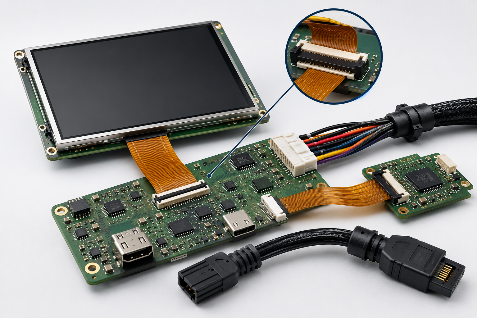
LCD cable and connector design is the process of selecting, routing, securing, and validating the interconnects that carry power, signals, touch data, and control lines between an LCD module and the host system.
Why LCD cable and connector design matters in OEM systems
LCD cable and connector design affects display stability, signal quality, assembly consistency, service access, and long-term reliability. Even when the LCD module and controller are correctly selected, poor interconnect design can cause flickering, image artifacts, intermittent operation, touch failures, EMI issues, or complete display loss.
In industrial, medical, defense, transportation, agricultural, food service, and rugged equipment, these failures can affect uptime, validation schedules, and field service plans. For reliability-first OEMs, interconnect design can also influence validation outcomes, uptime expectations, and long-term service stability. Therefore, engineers should treat LCD cable and connector design as a core part of system architecture, not as a late-stage mechanical detail.
Focus LCDs manufactures and supplies standard and custom LCD modules for OEM integration. In addition, Focus LCDs works with engineering teams to evaluate interface type, cable length, connector orientation, flex routing, mounting constraints, and lifecycle requirements. However, final system validation, certification, and compliance remain the responsibility of the OEM.
Why LCD Interconnect Design Matters
LCD interconnects create the physical link between the display module and the rest of the system. This link often carries high-speed video data, backlight power, touch controller signals, reset lines, enable lines, and ground references.
Because of this, cable and connector design affects both electrical and mechanical performance. A cable that works during bench testing may fail later if vibration, enclosure stress, repeated service handling, or poor routing changes the signal path.
For example, a loose connector can cause intermittent display output. Similarly, a flex cable with a tight bend radius can crack over time. In high-speed interfaces, poor cable layout can also increase noise, skew, or signal loss.
These risks connect closely to manufacturability planning, as discussed in LCD Design for Manufacturability in OEM Display Programs.
Common LCD Cable and Connector Failure Modes
Cable and connector issues often appear as display faults, even when the display module itself is functioning correctly.
| Failure Mode | Likely Interconnect Cause | System Impact |
|---|---|---|
| Flickering image | Loose connector, signal loss, poor shielding | Unstable display output |
| No display output | Unseated cable, wrong pinout, broken conductor | Failed startup or blank screen |
| Touch not responding | I2C line issue, interrupt line fault, connector strain | Loss of touch input |
| Image artifacts | High-speed signal degradation, skew, EMI coupling | Distorted or noisy image |
| Intermittent operation | Vibration, cable fatigue, poor retention | Field reliability risk |
| Backlight instability | Power conductor loss, weak crimp, voltage drop | Uneven or failed illumination |
Since many of these symptoms overlap with timing, power, and signal problems, engineers should evaluate the full interconnect path during debugging.
Connector Selection for LCD Modules
Connector selection affects assembly, serviceability, signal quality, and long-term durability.
Engineers should review:
• Contact pitch
• Pin count
• Locking or retention method
• Mating cycle rating
• Contact plating
• Connector height
• Orientation
• Cable insertion direction
• Production access
• Service access
Low-profile FFC and FPC connectors can support compact designs, while board-to-board or wire harness solutions may fit systems that need more mechanical separation or service flexibility. Engineers can reference TE Connectivity FPC connector resources when reviewing connector formats and compact interconnect options.
In rugged or serviceable equipment, retention is especially important. A connector without enough strain relief or locking support may pass early testing but fail after vibration, maintenance, or shipping stress.
LCD Cable and Connector Format Options
Different interconnect formats suit different mechanical, electrical, and service needs. Engineers should review connector format early so the display interface, enclosure, PCB layout, and assembly process work together.
| Cable or Connector Format | Where It Is Commonly Used | Key Design Considerations |
|---|---|---|
| FFC / FPC cable | Compact displays, tight enclosures, touch panels, small TFT modules | Bend radius, stiffener length, insertion force, connector latch, routing path |
| Wire harness | Systems needing service access, longer routing, or more mechanical separation | Strain relief, crimp quality, current rating, vibration support, routing clips |
| Board-to-board connector | Stacked PCB/display assemblies or compact internal modules | Alignment, stack height, mating tolerance, vibration, service access |
| Custom flex circuit | Thin assemblies, custom display modules, space-limited designs | Flex layer design, bend zones, impedance, tooling, lifecycle control |
| Shielded cable assembly | Higher-speed or EMI-sensitive systems | Shield termination, ground path, cable length, connector grounding |
Selecting the correct format helps reduce field risk and improves assembly consistency.
Cable Routing and Bend Radius
Cable routing affects both reliability and manufacturability. A cable path should support assembly without placing stress on the conductor, connector, display glass, or PCB.
Engineers should check:
• Bend radius
• Cable length
• Strain relief
• Routing path
• Contact with sharp edges
• Clearance from hot parts
• Clearance from moving parts
• Assembly access
• Service access
Tight bends can damage flexible circuits, especially near stiffeners or connector ends. In addition, repeated flexing can create conductor fatigue over time.
For flexible printed circuits, teams often reference standards such as ANSI IPC-2223 for flexible printed board design, especially when bend control, flex construction, and long-term reliability are important.
Signal Integrity in LCD Cable Design
LCD cable design becomes more critical as interface speed increases. MIPI DSI, LVDS, RGB, and eDP-style connections each place different demands on routing, shielding, impedance, and grounding.
High-speed display cables may require:
• Controlled impedance
• Matched pair routing
• Short cable length
• Strong ground reference
• Shielding where needed
• Proper connector pin assignment
• Reduced skew between signals
• Clean return paths
If these factors are ignored, the display may show artifacts, flicker, intermittent startup, or EMI sensitivity.
Signal behavior is closely related to MIPI DSI Signal Integrity Basics for Reliable LCD Integration and LCD Grounding and Return Path Design for EMI Stability in High-Speed Interfaces.
For high-speed connector design context, engineers may also reference the Samtec Signal Integrity Group resources.
Power and Backlight Cable Considerations
LCD interconnects do not only carry data. They may also carry backlight power, panel power, enable signals, reset lines, PWM dimming, and touch controller supplies.
Engineers should review:
• Current rating
• Voltage drop
• Ground return path
• Backlight current
• PWM dimming noise
• Power sequencing
• Connector derating
• Cable heating
Backlight power paths require special care because high current, PWM switching, and cable resistance can affect brightness stability and EMI behavior. If the power path is weak, the display may show dimming variation, flicker, or thermal stress.
These issues connect to LCD Power Integrity and Noise Management in Embedded Display Systems and LED Backlight Derating Curves for Long-Term LCD Reliability.
Mechanical Reliability in Rugged LCD Systems
In rugged systems, cables and connectors must survive vibration, shock, handling, temperature change, and enclosure stress. A cable that is electrically correct may still fail if the mechanical design does not protect it.
Key design factors include:
• Connector retention
• Cable strain relief
• Mounting support
• Vibration exposure
• Bend control
• Service handling
• Thermal expansion
• Enclosure pressure
Rugged systems should avoid unsupported cable spans, sharp routing turns, and connector loads caused by enclosure assembly. When possible, teams should secure cables so vibration does not transfer directly into connector contacts.
Mechanical reliability is discussed further in Rugged LCD Design for Harsh and Safety-Critical Applications and LCD Glass Selection for Vibration in Rugged OEM Systems.
Manufacturability and Assembly Considerations
Cable and connector design should support repeatable assembly. If a cable is hard to insert, easy to reverse, or difficult to inspect, production risk increases.
Manufacturing teams should be able to:
• Insert the cable without excessive force
• Verify correct orientation
• Inspect seating depth
• Access the connector during assembly
• Secure the cable without damaging it
• Replace the display when service is required
• Follow clear work instructions
A strong design reduces assembly variation and prevents small production differences from becoming field problems.
Focus LCDs can help OEM teams review display-centered cable and connector assumptions before release, including connector access, cable routing, strain relief, and service requirements.
This is why LCD cable and connector design should align with early design-for-manufacturability reviews.
LCD Cable and Connector Design Framework
A practical LCD interconnect framework includes five areas:
• Electrical design → signal speed, power, grounding, impedance
• Mechanical design → routing, bend radius, retention, strain relief
• Manufacturing design → access, inspection, orientation, work instructions
• Reliability design → vibration, fatigue, temperature, service handling
• Lifecycle design → availability, approved alternates, revision control
When teams review these areas together, they can reduce integration risk and improve long-term display reliability.
Focus LCDs can support OEM engineering teams as they review cable, connector, and display-interface requirements early in the integration process.
Cable and Connector Design Review Checklist
Before releasing an LCD design, engineers should confirm:
• The connector supports the required signal type and pin count
• Cable length matches electrical and mechanical limits
• Bend radius meets flex cable requirements
• Strain relief protects the connector and cable end
• Ground return paths support signal and power needs
• Backlight current stays within connector and cable limits
• Assembly workers can inspect connector seating
• Service teams can access the display without damage
• Approved alternates are documented for lifecycle support
• Validation uses the final cable length and routing path
This checklist helps teams catch interconnect issues before production release.
How to Debug LCD Cable and Connector Issues
Cable and connector faults can look like display, timing, or software problems. A step-by-step process helps narrow the root cause.
- Check whether movement changes the fault
Gently move the cable or enclosure area during testing. If the issue changes, inspect routing, bend radius, connector seating, and strain relief. - Inspect connector seating and orientation
Confirm latch position, cable insertion depth, pin alignment, and cable direction. - Verify electrical continuity and power paths
Check power, ground, backlight supply, touch lines, enable signals, and reset lines. - Compare with a known-good cable or connector
Use a known-good assembly to separate cable faults from display, controller, or firmware issues. - Measure high-speed signal behavior when needed
For MIPI DSI, LVDS, RGB, or similar interfaces, verify signal quality, skew, grounding, and EMI behavior. - Repeat testing under real operating conditions
Test under vibration, temperature, and full system load if the product will operate in rugged or safety-critical environments.
This process helps separate interconnect faults from timing, power, or firmware issues. Related root cause methods are discussed in LCD Failure Analysis in Embedded Systems.
Common LCD Cable and Connector Design Mistakes
Engineers often encounter avoidable interconnect issues during development.
Common mistakes include:
- Using a cable that is too long for the interface speed
- Routing flex cables around sharp corners
- Ignoring strain relief near connector ends
- Choosing connectors without enough retention
- Allowing enclosure pressure to load the cable
- Skipping vibration testing
- Changing cable suppliers without validation
- Validating with a prototype cable instead of the final cable
- Forgetting to document approved alternates
Although these mistakes may seem small, they can create intermittent failures that are difficult to debug later.
Focus LCDs Engineering Approach
Focus LCDs manufactures and supplies standard and custom LCD modules and works with OEM engineering teams to align display interconnect design with electrical, mechanical, and lifecycle needs.
This includes support for cable design coordination, connector planning, display interface selection, custom module configuration, cover glass integration, mechanical stack-up, and long-term program requirements.
By reviewing cable and connector requirements early, Focus LCDs helps OEM teams reduce integration risk, improve assembly consistency, and support reliable display operation in rugged, regulated, and long-lifecycle systems. This engineering-led display integration support is intended for OEM teams that require long-term program stability rather than lowest-cost sourcing.
Scope Boundary and Compliance Responsibility
Focus LCDs provides LCD modules and engineering guidance for integration. However, Focus LCDs does not control final OEM cable routing, enclosure design, system validation, regulatory certification, or compliance testing.
OEMs remain responsible for validating display performance, safety, and compliance within their complete system architecture.
Contact Focus LCDs
If you are developing a system where cable routing, connector selection, signal integrity, or long-term display reliability is critical, Focus LCDs can support display selection, custom module planning, and integration strategy.
Contact Focus LCDs: https://focuslcds.com/contact
FAQ: LCD Cable and Connector Design
Why does LCD cable and connector design matter?
LCD cable and connector design affects signal quality, power delivery, assembly consistency, service access, and long-term display reliability.
What causes LCD cable failures?
Common causes include tight bend radius, poor strain relief, loose connectors, vibration, cable fatigue, wrong pinout, and uncontrolled supplier changes.
How can cable routing affect display performance?
Poor routing can increase signal loss, EMI coupling, skew, or mechanical stress, which may cause flickering, image artifacts, touch faults, or intermittent operation.
What should engineers check when choosing an LCD connector?
Engineers should review pin count, pitch, retention method, mating cycle rating, orientation, signal type, current rating, and production access.
Why is strain relief important for LCD cables?
Strain relief protects the connector and cable end from stress caused by vibration, assembly handling, service access, or enclosure movement.
When should LCD cable design be validated?
LCD cable design should be validated before production release using the final cable length, routing path, connector type, and enclosure configuration.
Conclusion: Interconnect Design Protects LCD Reliability
LCD cable and connector design directly affects display stability, manufacturability, and long-term reliability.
By reviewing cable routing, connector retention, signal integrity, power delivery, strain relief, and lifecycle needs early, OEM teams can reduce validation delays and prevent field failures.
In rugged and reliability-first systems, the display interconnect is not a minor hardware detail. It is a core part of successful LCD integration.

