

LCD Gasket and Enclosure Sealing Design for Rugged OEM Displays
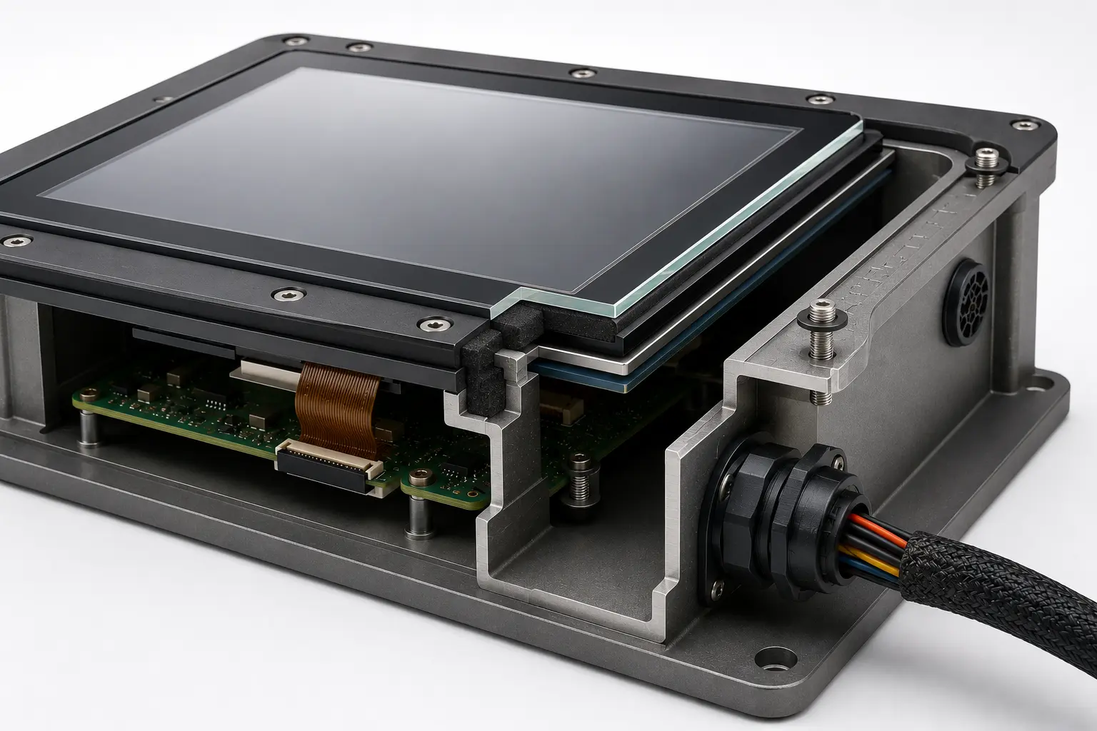
What is LCD gasket and enclosure sealing design?
LCD gasket and enclosure sealing design is the process of selecting and placing seals, gaskets, vents, adhesives, and enclosure interfaces to protect a display system from dust, moisture, vibration, cleaning exposure, and mechanical stress.
Why LCD gasket and enclosure sealing design matters in OEM systems
LCD gasket and enclosure sealing design affects display reliability, field durability, optical performance, service life, and system validation. A display may meet electrical, optical, and mechanical requirements, but still fail in the field if the enclosure does not protect the display stack from water, dust, pressure, vibration, or repeated cleaning.
In industrial, medical, defense, transportation, agricultural, food service, and outdoor systems, sealing design can affect uptime, service planning, and long-term reliability. This is especially important for OEMs building displays into systems where downtime, ingress, or field rework can carry safety, compliance, or operational consequences. Therefore, engineers should treat gasket and enclosure sealing as part of the complete display architecture, not as a final enclosure detail.
Focus LCDs manufactures and supplies standard and custom LCD modules for OEM integration. In addition, Focus LCDs works with engineering teams to review display stack-up, cover glass, cable routing, mounting features, gasket interfaces, and environmental requirements. However, final enclosure validation, regulatory certification, sealing performance, and compliance remain the responsibility of the OEM.
Key Takeaways for OEM Engineers
• Sealing design affects display reliability, touch performance, optical quality, and field durability.
• Gasket compression must protect against ingress without stressing the cover glass or LCD stack.
• Cable exits, vents, fasteners, and enclosure seams must be reviewed as part of the full sealing path.
• Cleaning chemicals, humidity, vibration, and thermal cycling can change sealing behavior over time.
• Final sealing performance depends on the complete OEM system, not the display module alone.
Why Sealing Matters in LCD Integration
An LCD module often sits at the boundary between the outside environment and the internal electronics. This makes the display area one of the most important sealing points in the full system.
Poor sealing can allow dust, moisture, cleaning fluid, or debris to enter the enclosure. In addition, uneven gasket pressure can stress the cover glass, touch panel, LCD glass, flex cable, or optical bond line.
For example, a display may pass bench testing but fail after washdown, vibration, thermal cycling, or field handling. Similarly, a seal that works during prototype assembly may become inconsistent once production volume increases.
Sealing decisions are closely related to display manufacturability, as discussed in LCD Design for Manufacturability in OEM Display Programs.
Common LCD Sealing Failure Modes
Sealing problems often appear as optical, mechanical, electrical, or field reliability issues.
| Failure Mode | Likely Sealing Cause | System Impact |
|---|---|---|
| Fogging behind the cover glass | Moisture ingress or poor venting | Reduced readability |
| Dust inside the display area | Weak gasket seal or assembly gap | Cosmetic and optical failure |
| Touch panel instability | Moisture, enclosure pressure, or grounding issue | Poor user input |
| Cracked cover glass | Uneven compression or edge loading | Mechanical failure |
| Intermittent display operation | Fluid ingress near cable or PCB | Field reliability risk |
| Optical distortion | Gasket pressure on bonded stack | Reduced display quality |
| Corrosion | Moisture ingress or chemical exposure | Long-term system damage |
Because these symptoms can overlap with optical bonding, cable, power, or touch problems, engineers should evaluate the full display enclosure interface during root cause analysis.
Gasket Function in Display Systems
A gasket does more than fill a gap. It helps control how the display stack interacts with the enclosure, environment, and assembly process.
A display gasket may need to:
• Block dust
• Limit water ingress
• Control compression
• Reduce vibration transfer
• Protect glass edges
• Support cover glass fit
• Manage assembly variation
• Maintain service access
• Separate materials
• Help control airflow or venting
The gasket must match the enclosure shape, display stack-up, fastener pattern, material behavior, and expected field environment.
Gasket Material Selection
Gasket material affects sealing performance, compression behavior, chemical resistance, temperature range, and long-term reliability.
Common gasket material options include:
• Silicone foam
• EPDM foam
• Poron-type urethane foam
• Sponge rubber
• Solid elastomer
• Conductive elastomer
• Form-in-place gasket material
• Adhesive-backed foam tape
Each material has tradeoffs. Some materials compress easily and support low closure force. Others provide stronger chemical resistance, better temperature performance, or EMI shielding support.
For general sealing design context, engineers may reference the Rogers BISCO Technical Sealing Design Guide.
Compression Set and Long-Term Seal Performance
Gasket performance depends on how well the seal maintains pressure over time. If a gasket takes a permanent set, it may no longer press firmly against the enclosure or cover glass.
Engineers should review:
• Compression force
• Compression set
• Material thickness
• Closure force
• Fastener spacing
• Temperature exposure
• Chemical exposure
• Aging behavior
• Service cycles
• Assembly variation
Too little compression can create leaks. Too much compression can stress the display stack, distort the optical area, or damage the cover glass. Therefore, gasket design must balance sealing force with display protection.
Enclosure Ratings and Display Sealing
Many OEM systems need a defined level of protection against dust, water, cleaning fluid, impact, or environmental exposure. Display sealing often plays a key role in meeting those goals.
Engineers may reference NEMA enclosure type guidance when reviewing environmental protection categories for equipment enclosures.
For certification context, UL electrical enclosure and component certification resources provide useful guidance on Type ratings, IP Code ratings, and IK impact ratings.
However, a display module alone does not determine the final enclosure rating. The complete OEM system, including enclosure design, fasteners, gasket compression, cable exits, vents, seams, and assembly process, must be validated by the OEM.
Display Stack-Up and Gasket Placement
Gasket placement affects the mechanical load path around the display. Poor placement can create pressure points that damage the LCD, touch sensor, cover glass, or optical bond.
Engineers should review:
• Gasket location
• Gasket width
• Compression height
• Glass edge clearance
• Bond line location
• Active area clearance
• Touch sensor position
• Cover glass overhang
• Enclosure lip geometry
• Fastener spacing
The gasket should support sealing without loading the active display area or creating uneven stress across the front stack.
These decisions connect closely to LCD Optical Bonding and Cover Glass Design for OEM Displays.
Cover Glass, Touch Panels, and Sealing
Cover glass design and gasket design must work together. The glass thickness, edge finish, coating, ink border, touch sensor, adhesive, and enclosure geometry all affect seal quality.
A gasket that presses too close to the active area can cause optical distortion. Likewise, a gasket that presses unevenly near the edge can increase the risk of cracking, delamination, or touch instability.
Touch displays require special care because water, gloves, cleaning fluid, and enclosure grounding can affect touch behavior. Therefore, teams should validate sealing, touch response, and display readability using the final cover glass and enclosure design.
Cable Exits and Connector Sealing
Display cables often create sealing risk because they pass from the display area into the system electronics. If cable exits are not protected, moisture and dust can reach connectors, PCBs, or backlight circuits.
Engineers should check:
• Cable exit location
• Flex cable strain relief
• Connector position
• Grommet design
• Adhesive seal areas
• Cable bend radius
• Service access
• Water path risk
• Condensation path risk
• Assembly repeatability
Cable and connector planning is discussed further in LCD Cable and Connector Design for Reliable OEM Integration.
EMI Shielding and Environmental Sealing
Some display systems need both environmental sealing and EMI control. In these cases, the gasket may need to support sealing, grounding, and shielding at the same time.
Conductive gaskets can help connect enclosure sections, reduce EMI leakage, and support grounding continuity. However, they must also match the compression force, surface finish, corrosion risk, and enclosure material.
Engineers may reference Parker Chomerics EMI gasket resources when reviewing conductive gasket options for EMI shielding and environmental sealing.
Grounding and EMI behavior are also discussed in LCD Grounding and Return Path Design for EMI Stability in High-Speed Interfaces and EMI EMC in LCD Modules: Display-Level Design Considerations.
Venting and Pressure Equalization
A fully sealed enclosure can create pressure problems when temperature or altitude changes. Pressure differences may stress the gasket, cover glass, touch panel, or enclosure seams.
Venting may be needed when the system faces:
• Outdoor temperature swings
• Altitude change
• Rapid thermal cycling
• Washdown exposure
• Sealed battery compartments
• Large cover glass areas
• Flexible enclosure sections
A vent can help reduce pressure stress while still supporting environmental protection. However, vent selection and placement must match the required sealing level, airflow path, and contamination risk.
Chemical and Cleaning Exposure
Medical, food service, industrial, and transportation systems often face repeated cleaning. Cleaning chemicals can affect gasket materials, coatings, adhesives, and enclosure finishes.
Engineers should review exposure to:
• Alcohol-based cleaners
• Detergents
• Disinfectants
• Oils
• Grease
• Fuel or solvents
• Food residue
• Salt spray
• UV exposure
• High humidity
Material compatibility should be reviewed early because chemical damage can cause swelling, cracking, softening, discoloration, seal loss, or adhesive failure.
Thermal and Environmental Stress
Temperature changes can affect gasket compression, enclosure fit, adhesive behavior, and moisture control.
Common thermal risks include:
• Expansion mismatch
• Gasket hardening
• Seal relaxation
• Condensation
• Adhesive softening
• Cover glass stress
• Coating wear
• Edge seal failure
In sealed display systems, heat from the backlight, electronics, and enclosure can increase stress on the gasket and optical stack. Related thermal planning is discussed in LCD Thermal Modeling in Enclosures for OEM Reliability.
Gasket and Sealing Design Framework
A practical LCD gasket and enclosure sealing framework includes five areas:
• Environmental design → dust, moisture, chemicals, UV, cleaning
• Mechanical design → compression, glass loading, vibration, enclosure fit
• Optical design → active area clearance, distortion, fogging, visibility
• Electrical design → cable exits, grounding, EMI shielding, connector protection
• Lifecycle design → material availability, approved changes, service access
When teams review these areas together, they can reduce sealing risk and improve long-term display reliability.
Focus LCDs can help OEM teams review these display-specific sealing factors early so gasket design, cover glass, cable routing, optical stack-up, and enclosure requirements are aligned before release.
LCD Gasket and Sealing Risk Factors
| Risk Factor | Potential Impact | Design Review Action |
|---|---|---|
| Low gasket compression | Dust or moisture ingress | Review gasket height, closure force, and tolerance stack |
| Excess gasket compression | Glass stress or optical distortion | Check compression limits and active area clearance |
| Poor cable exit sealing | Fluid ingress near electronics | Add strain relief, grommet, or controlled cable path |
| Chemical mismatch | Swelling, cracking, or seal loss | Validate gasket and adhesive material compatibility |
| Poor venting | Fogging or pressure stress | Review vent placement and pressure equalization |
| Uneven enclosure fit | Seal gaps or cover glass loading | Check fastener spacing, enclosure flatness, and gasket path |
| Uncontrolled material change | Revalidation or field risk | Document material choices, alternates, and change control |
This table helps engineers connect sealing symptoms to design decisions before validation begins.
Validation and Test Planning
Sealing design should be validated with the final display, gasket, enclosure, cable routing, fasteners, and assembly process. Prototype shortcuts can hide real sealing problems.
Validation planning may include:
• Dust exposure testing
• Water spray or washdown testing
• Humidity testing
• Thermal cycling
• Chemical exposure testing
• Vibration testing
• Impact testing
• Cleaning process review
• Touch performance testing
• Visual inspection after exposure
For rugged systems, teams should test the complete display area under real operating conditions, not only the gasket material by itself.
Mechanical and environmental design considerations are also discussed in Rugged LCD Design for Harsh and Safety-Critical Applications and LCD Glass Selection for Vibration in Rugged OEM Systems.
Manufacturing and Assembly Control
A sealing design must be repeatable in production. Even a well-chosen gasket can fail if assembly teams place it incorrectly, compress it unevenly, or damage it during installation.
Manufacturing teams should review:
• Gasket placement method
• Adhesive liner removal
• Assembly sequence
• Fastener torque
• Compression control
• Inspection points
• Rework limits
• Handling instructions
• Packaging protection
• Service replacement process
Clear work instructions help reduce assembly variation and protect long-term sealing performance.
Lifecycle and Material Control
LCD gasket and enclosure sealing design also requires lifecycle planning. Material choices should account for long-term availability, approved alternates, revision control, and controlled supplier changes.
For long-lifecycle OEM programs, changes to gasket material, adhesive backing, cover glass, vent material, or enclosure finish may affect sealing behavior and validation status. Because of this, engineers should document key material choices and review any change before release.
For long-life OEM programs, this review can also help protect BOM stability, approved material choices, and controlled supplier transitions.
Common LCD Gasket and Sealing Design Mistakes
Engineers often encounter avoidable sealing issues during display integration.
Common mistakes include:
• Treating the gasket as a late-stage enclosure detail
• Compressing the gasket too close to the active display area
• Ignoring cable exit sealing
• Choosing gasket material without chemical review
• Validating with prototype enclosure parts
• Skipping thermal cycling or humidity testing
• Overlooking venting and pressure change
• Allowing uneven fastener torque
• Changing gasket suppliers without revalidation
• Missing service replacement instructions
Although these issues may seem small during development, they can create field failures, cosmetic defects, and late-stage redesign.
How to Debug LCD Sealing Issues
Sealing problems can look like display, optical, touch, or electrical failures. A structured process helps narrow the root cause.
- Identify the visible symptom
Check whether the issue appears as fogging, dust, water spots, corrosion, glass stress, touch instability, or display failure. - Inspect the gasket path
Look for gaps, uneven compression, wrinkles, cuts, adhesive lift, or placement errors. - Review enclosure loading
Check fastener torque, enclosure flatness, gasket compression, and cover glass pressure. - Check cable exits and vents
Inspect cable routing, grommets, vent placement, connector areas, and possible water paths. - Compare with a known-good assembly
Use a known-good sealed unit to separate gasket, enclosure, display, and assembly issues. - Repeat testing under real conditions
Test with final cleaning methods, humidity, thermal cycling, vibration, and full system operation.
This process helps separate enclosure sealing problems from LCD module, optical bonding, touch controller, or cable issues.
Focus LCDs Engineering Approach
Focus LCDs manufactures and supplies standard and custom LCD modules and works with OEM engineering teams to align display sealing, cover glass, cable routing, mechanical stack-up, and lifecycle requirements.
This includes support for custom LCD modules, cover glass planning, gasket interface review, cable coordination, touch integration, optical stack-up review, mounting features, and display-related subassemblies where appropriate.
By reviewing gasket and enclosure sealing requirements early, Focus LCDs helps OEM teams reduce integration risk, improve durability, and support reliable display operation in rugged, regulated, and long-lifecycle systems. This engineering-led display integration support is intended for OEM teams that require long-term program stability rather than lowest-cost sourcing.
Scope Boundary and Compliance Responsibility
Focus LCDs provides LCD modules and engineering guidance for integration. However, Focus LCDs does not control final OEM enclosure design, gasket compression, sealing validation, cleaning process validation, regulatory certification, or compliance testing.
OEMs remain responsible for validating sealing performance, display safety, and compliance within their complete system architecture.
Contact Focus LCDs
If you are developing a display system where sealing, durability, washdown exposure, touch performance, or rugged reliability is critical, Focus LCDs can support display selection, custom module planning, and integration strategy.
Contact Focus LCDs: https://focuslcds.com/contact
FAQ: LCD Gasket and Enclosure Sealing Design
What is LCD gasket and enclosure sealing design?
LCD gasket and enclosure sealing design helps protect a display system from dust, moisture, cleaning exposure, vibration, and mechanical stress.
Why does gasket design matter for LCD modules?
Gasket design affects sealing, cover glass stress, touch performance, optical quality, cable protection, and long-term display reliability.
Can too much gasket compression damage an LCD?
Yes. Excess compression can stress the cover glass, touch panel, optical bond, or LCD glass and may cause distortion, cracks, or touch issues.
How does sealing affect touch displays?
Poor sealing can allow moisture or cleaning fluid near the touch stack, while uneven enclosure pressure can affect touch response and display readability.
What should engineers review when sealing an LCD enclosure?
Engineers should review gasket material, compression, enclosure flatness, cable exits, cover glass fit, venting, chemical exposure, and validation requirements.
Does a display module determine the final IP or enclosure rating?
No. The final enclosure rating depends on the complete OEM system, including enclosure design, gaskets, vents, fasteners, cable exits, and validation testing.
When should LCD sealing design be validated?
LCD sealing design should be validated before production release using the final display, gasket, enclosure, cable routing, fasteners, and assembly process.
Conclusion: Sealing Design Protects Display Reliability
LCD gasket and enclosure sealing design directly affects durability, readability, touch performance, and long-term reliability.
By reviewing gasket material, compression, enclosure fit, cable exits, venting, chemical exposure, and lifecycle needs early, OEM teams can reduce validation delays and prevent field failures.
In rugged and reliability-first systems, sealing is not only an enclosure detail. It is a core part of successful LCD integration.

